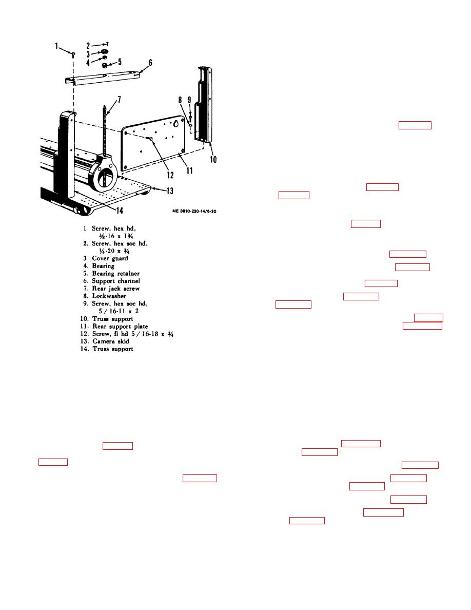
Clean the truss supports plate and channel with a cleaning
solvent and a small brush. Wipe the bearing, bearing retainer,
and cover guard with a cloth dampened with cleaning solvent.
Wipe parts thoroughly with a dry, clean cloth. Inspect the truss
supports and channel for cracks, breaks, and corrosion. Check
the rear support plate for bends and distortion. Examine the
bearing retainer, and outer race of bearing for scoring. Repack
bearing. Replace all defective parts.
6-41. Truss Support Reassembly and Installation
the camera skid (13) and retain each with three lockwashers (8)
and screws (91. Install the support channel (6) on truss
supports with four screws (1). Place bearing retainer (5) and
bearing (4) in channel over rear jack screw (71. Retain with
cover guard (3) and four screws (2). Install the rear support
plate (ll) with four screws (12).
support (5, fig. 6-19) with four screws placed inside of breaker.
Position the interlock switch (6) on rim of truss support and
retain with two screws.
channel (1 l and install with two screws (2). Position and clamp
filter (4) on filter bracket (3) and retain with screw (2).
camera skid and secure with mounting screws. Install the
vacuum turbo-compressor assemblies (para 6-4. b. ).
contactor (para 6-36. a. ). Dress all wire leads.
and install box with four screws (6, fig. 4-15).
Figure 6-20. Truss support assembly, exploded view.
6-40. Truss Support Cleaning and Inspection
Section XI. CAMERA RAIL, TUBE AND DRIVESCREWS
6-42. Description
6-43. Camera Rail, Tube, and Drivescrew Removal
The camera tube (7, fig. 1-2) is the bed of the camera,
support assembly (para 4-36. b. ).
supporting the copyboard (2), lensboard (4l, and the camera rail
(5. fig. 1-1). The tube flanges welded to the ends of the
camera tube support and aline it with the related supporting
structures of the unit. The camera rail (7, fig. 6-19) is
the copyboard carriage assembly (para 6-18).
continuously fastened to the tube (12) and is dependent upon it
for its rigidity and alignment. The camera rail is machined with
beveled guides to provide for accurate support of the movable
lens-board and copyboard carriages over their entire range of
travel.
focusing glass (para 4-34
6-18


