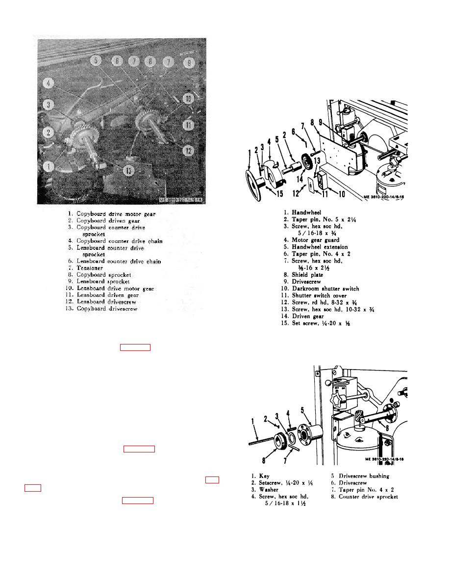
drivescrew (6\. Tap off sprocket; pry out key (1l, and slide off
washer (31.
h. Remove six screws (4l, securing drivescrew bushing
(S) to camera and slide off bushing.
i. Repeat g and h above for remaining drive mechanism.
Figure 6-14. Camera drivescrews.
6-30. Drive Mechanism Removal and Disassembly
Figure 6-15. Drive mechanism, exploded
view,
handwheel, extension, drive screw gear.
and slide off handwheel (1).
b Remove two screws (3), securing motor gear guard (4)
to shield plate (8) and lift off guard.
c Drive out tapered pin
t2).
securing
handwheel
extension (5) to drive screw (9).
d Drive out tapered pin (6l, securing driven gear (14) to
drivescrew and tap off gear.
e Repeat the above operations on the remaining drive
mechanism.
(8) to back support plate and lift out plate. Remove two screws
(12) to detach cover (1 1) from shutter switch (101. Remove
two screws (13) to detach shutter switch from shield plate (8 I.
Detach wires from switch. Remove counter drive chain (4, fig.
tapered pin (7l, securing counter drive sprocket (8) to
Figure 6-16. Drive mechanism, exploded
view,
counter drive sprocket, drive-crew bushing.
6-14


