
Section VI. LENS BOARD ASSEMBLY
6-21. Description
6-22. Lensboard Disassembly
The lensboard assembly is mounted on the lens-board carriage
The lensboard is partially disassembled as it is removed from
assembly by two side frames.
The lensboard provides
the lensboard carriage assembly.
horizontal and vertical movement for the lens, and is controlled
from the darkroom end of camera and from the lensboard
location. The darkroom control knobs control the lens by the
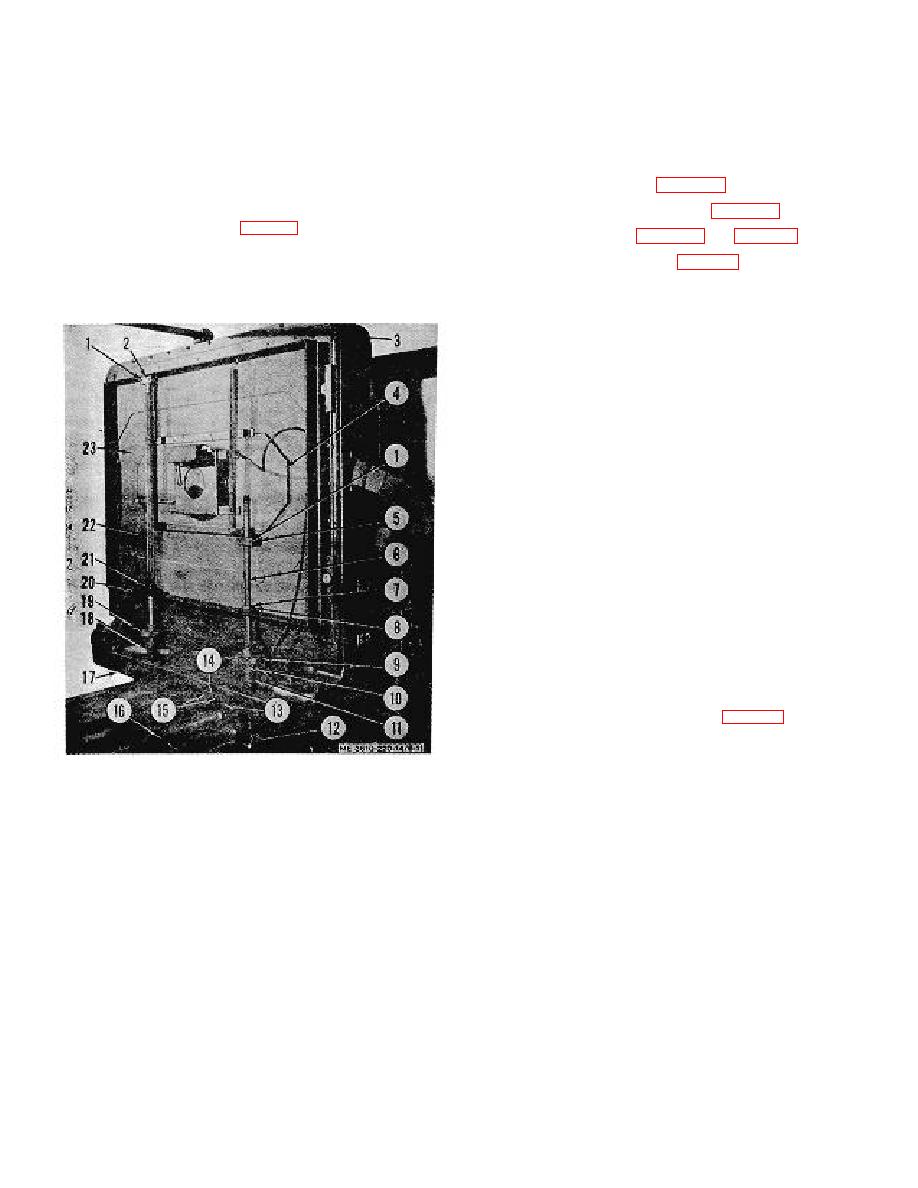
action of the driven gears (12, fig. 6-11) which operate from the
lensboard control shafts (16). The lensboard control shafts
move the horizontal drive shaft (22) and vertical drive shaft (6)
which, in turn, move the inner lensboard frame (4). The lens
vertical drive nut (5) to lensboard (231. Loosen setscrew
and shutter assembly are mounted on opposite sides of the
) on vertical drive shaft collar (7)
frame.
e. Drive out tapered pin (10) from universal joint (111.
While backing off vertical adjustment handwheel (9l, elide out
vertical drive shaft assembly.
f. Remove four screws (1, fig. 6 l 1), securing upper and
lower bearing blocks (2) and (20) to lensboard. Loosen
setscrew (1) on collar (21) of horizontal drive shaft (22). Drive
out tapered pin (10) from universal joint (18), and elide out
horizontal drive shaft assembly after backing off horizontal
adjustment handwheel (19).
g. Remove four screws (3), securing lensboard assembly
to carriage frames. Lift off lensboard.
6-23. Lensboard Cleaning and Inspection
Clean the lensboard with a cleaning solvent and a clean cloth.
Clean the shafts and collars with a em all brush. Dry the
lensboard with a soft, clean cloth. Use air hose to dry recessed
surfaces and threaded parse. Inspect the lensboard and shafts
for distortion and bends. Check parts for stripped threads and
wear. Replace all defective parse.
6-24. Lensboard Reassembly
a Reassembly and Installation.
(1) Position lensboard (23, fig. 6-11) on carriage
frames and secure with four screws (3).
(2) Insert vertical drive shaft (6) in position an d
turn on vertical adjustment handwheel (9 J. Position drive nut
Figure 6-11. Lensboard assembly, installed.
(5) on lensboard and secure with
6-11
