
4-37. Bellows
d. Installation.
(1) Insert the inner tube (5, fig. 4-20) in outer tube
heavy rubberized duck material to form a single accordion
(3) so that it protrudes beyond bevel end of outer tube. Attach
bellows unit capable of expanding and contracting within the
hooked wire to end of internal spring (6), and pull spring
full range of reproduction ratios. Two clamp and screw
through inner tube (5) until one looped end of 'spring extends
assemblies (6), one on each side of the bellows end frame (5),
just outside of end to be capped. Rotate spring slightly until its
attach the bellows to the camera back. On the opposite end the
loop is at right angle to the screw securing the cap. Press on
bellows is attached to the lensboard (1) by four screws equally
cap (2), insert screw (1) (through cap, tube, and spring loop),
spaced on the bellows end frame (2).
and turn screw in tight.
b. Removal.
(2) Insert telescoping tubing through tube guide (2,
(1) Operate lensboard to extend bellows (7). Then
remove hex nuts (11, fig. 4-19) and screws (9), supporting
the tube. Grasp the wire still hooked to the loop of internal
bellows.
spring (6), and draw the spring until it extends a foot or so out
(2) Detach the bellows (7, fig. 4-18) from the
of the tube (3). Apply a little grease to the spring, then ease the
camera back by loosening clamp and screw assembly (6) on
wire gradually until the spring loop is in line with the screw hole.
each side of bellows end frame (5).
Insert screw (1) through tube flange (4), outer tube (3), and
spring (6) and tighten screw.
(3) Remove four screws (3, fig. 4-18), two on each
side of the bellows end frame (2), to release bellows from the
(3) Attach flange plate (6, fig. 4-19) with two screws
lensboard (1).
(7). Then place telescoping tube assembly over bellows, and
screw on tube guide (2) with screws (12), and flange (5) to
(4) Release the bellows strap (8) by removing 2
flange plate (6) with screws (8).
screws from the footman loop.
(4) Line up roller carriers (3) with connector plate
(10), and install screw (9) and nut (11) to support bellows.
c. Cleaning, Inspection, and Repair. Clean the bellows
with a damp cloth. If necessary, use a little soap, and follow
with a damp cloth again. Be sure to clean the inner crevices.
Clean the bellows end frames thoroughly, being certain to clean
threaded holes. Inspect the bellows for cracks, tears, and
holes. Examine for overall wearing of fabric. Repair small
holes and cracks with patches of rubberized duck material and
the appropriate rubber adhesive cement. Expand the bellows to
its fullest extent and apply a light coat of neoprene compound to
the fabric to prevent cracking and dry rot. Replace bellows if
beyond repair.
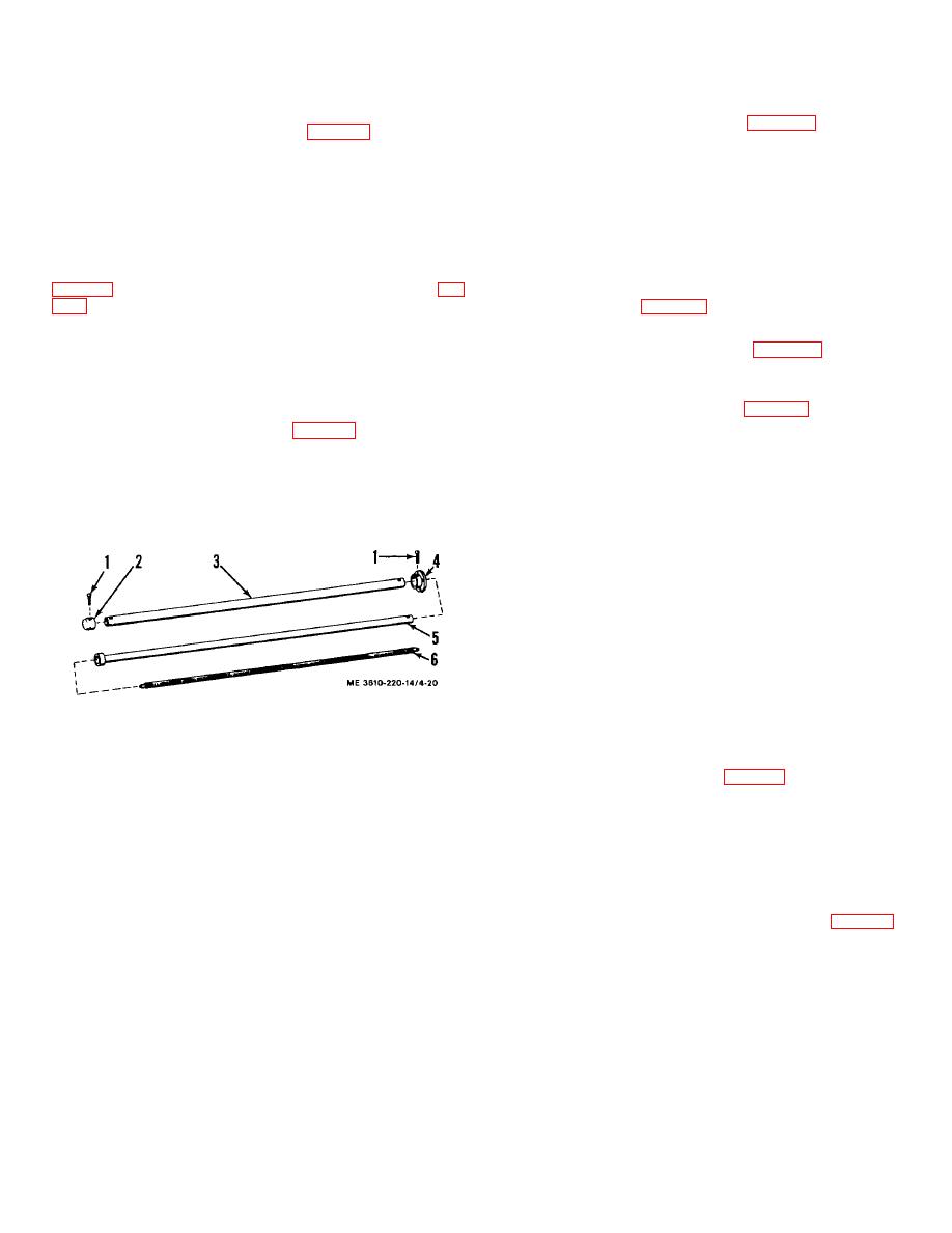
1.
Screw, rd hd, 10-32 x 1 /4
2.
Inner tube cap
d. Installation.
3.
Outer tube
4.
Tube flange
(1) Install the bellows (7, fig. 4-18) on the lensboard
5.
Inner tube
(1) with four screws (3).
6.
Internal spring
Figure 4-20. Telescoping tubes, exploded view.
(2) Connect the bellows to the camera back by
connecting the clamp and screw (6) to the bellows end frame
(5).
(3) Install the bellows strap (8) by connecting the
footman loop with 2 screws (9) to the bellows end frame (2).
(4) Support bellows on roller carriers (3, fig. 4-19)
by inserting screws (9) through carriers and connector plates
(10), and then attach hex nuts (11).
4-22
