4-46. Aerial Film Brackets
copying. One of the brackets in each set contains a crank to
roll film on the aerial film spool.
move aerial film bracket (6) to slot (5) of slide bar (2) and
remove.
c. Cleaning and Inspection. Clean the aerial film bracket
with a cleaning solvent and clean cloth. Dry bracket thoroughly
with a clean cloth. Inspect the bracket for breaks in casting,
crank for freedom of movement, and lockscrews. Replace
aerial film bracket if defective.
in slot (5) of slide bar (2), and move the bracket to
accommodate the film spool. Tighten the bracket lockscrew
(3).
4-47. Diffusers
a. Description. The transparency holder assembly
contains two glass diffusers to provide a distribution of light for
copying transparencies. The inner diffuser (13, fig. 4-22), a
5/16 inch plate opal glass adjacent to the light box assembly
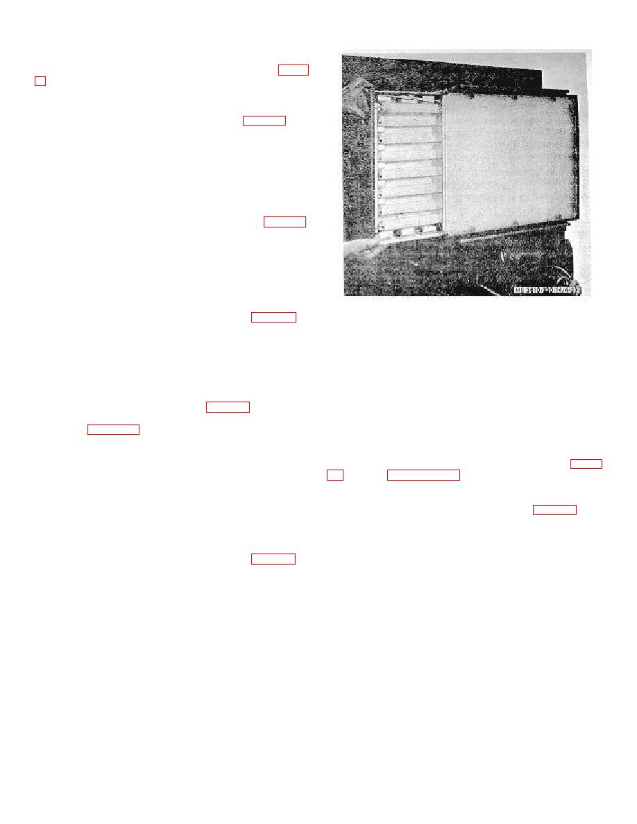
Figure 4-23. Removing light box assembly from
(14), diffuses the light to eliminate hot spots. The 5/16 inch
transparency holder.
polished plate diffuser (12), forming the face of the
transparency holder, also diffuses the light, providing an even
4-48. Light Box Assembly
distribution of light over the entire area.
a. Description. The light box assembly (fig. 424) is the
b. Removal.
light source for positive transparency and aerial film
reproduction. Ten fluorescent tubes in the light box are wired in
(1) Remove two screws (11, fig. 4-22) and slide the
a parallel circuit. Ten ballasts, internally mounted, stabilize the
light box assembly from the transparency holder housing (10),
flow of electricity to the fluorescent tubes. The starter for each
as shown in figure 4-23.
tube is adjacent to the tube it controls. A terminal block is
provided to facilitate wiring and connections.
(2) Slide the polished plate glass (12, fig. 422) and
opal glass diffuser (13) from the transparency holder housing
(10).
c.
Cleaning and Inspection. Clean the diffuser glass
c. Disassembly.
with a cloth saturated in acetone. Wipe dry with a clean, soft
cloth. Inspect the glass for cracks and chipping on edges.
(1) Remove the fluorescent tube (1, fig. 4-24) from
Replace gasket if cracked or chipped.
light box by rotating it in its sockets (9).
(2) Remove the starter by depressing, turning
d. Installation.
counterclockwise, and then pulling out. Trace wires of starter
(1) Slide the opal glass diffuser ( 13, fig. 4-22) in
socket (11}) to the terminal block (6) and detach wires. Release
the groove on the transparency holder housing (10). Similarly
two screws (10) and nuts to remove starter socket.
position the polished plate glass (12) in the housing.
(3) Trace wires of fluorescent tube socket (9) to the
(2) Slide the light box assembly (14) in the housing
terminal block and detach them. Remove tube socket by
and retain with two screws (11).
releasing two screws (10).
(4) Disconnect wires of ballast (2) from terminal
block and remove ballast by releasing two lockwashers (4), and
screws (3).
4-26


