Section X. MAINTENANCE OF BELLOWS ASSEMBLY
4-35. Description
(2) Release the tube flange (5) from flange -plate
The bellows assembly is an expandable component of the
(6) by removing four screws (8). Release the flange plate (6)
camera, connecting the camera back to the lensboard and
with two screws (7).
supported at its ends by two metal end frames (2 and 5, fig. 4-
(3) Bend one end of a length of wire (about 1 / 16-
in. dia.) into a hook, and hook onto loop of internal spring (6,
assembly (4) and its roller carriers reinforce the bellows, and
are supported by the lensboard and camera back.
spring with wire, remove screw (1) and ease spring into tubing.
Remove screw (1) to release inner tube cap (2) at front end of
telescoping inner tube (5). Then pull out spring with wire. Push
out inner tube from the outer tube (3) from end that was
attached to the flange (4).
(4) Disconnect the roller carrier (3, fig. 4-19) from
connector plate (10) by removing screw (9) and hex nut (11).
Remove the other five roller carriers in the same manner.
c. Cleaning and Inspection. Wash the parts thoroughly
with cleaning solvent and clean cloth. Clean inner surfaces and
threaded areas and dry parts thoroughly with a clean cloth.
Inspect components for bends, cracks, and breaks. Examine
the tube for distortion and corrosion on outer surface. Check
the roller carriers for burrs or pitted spots. Replace all defective
parts.
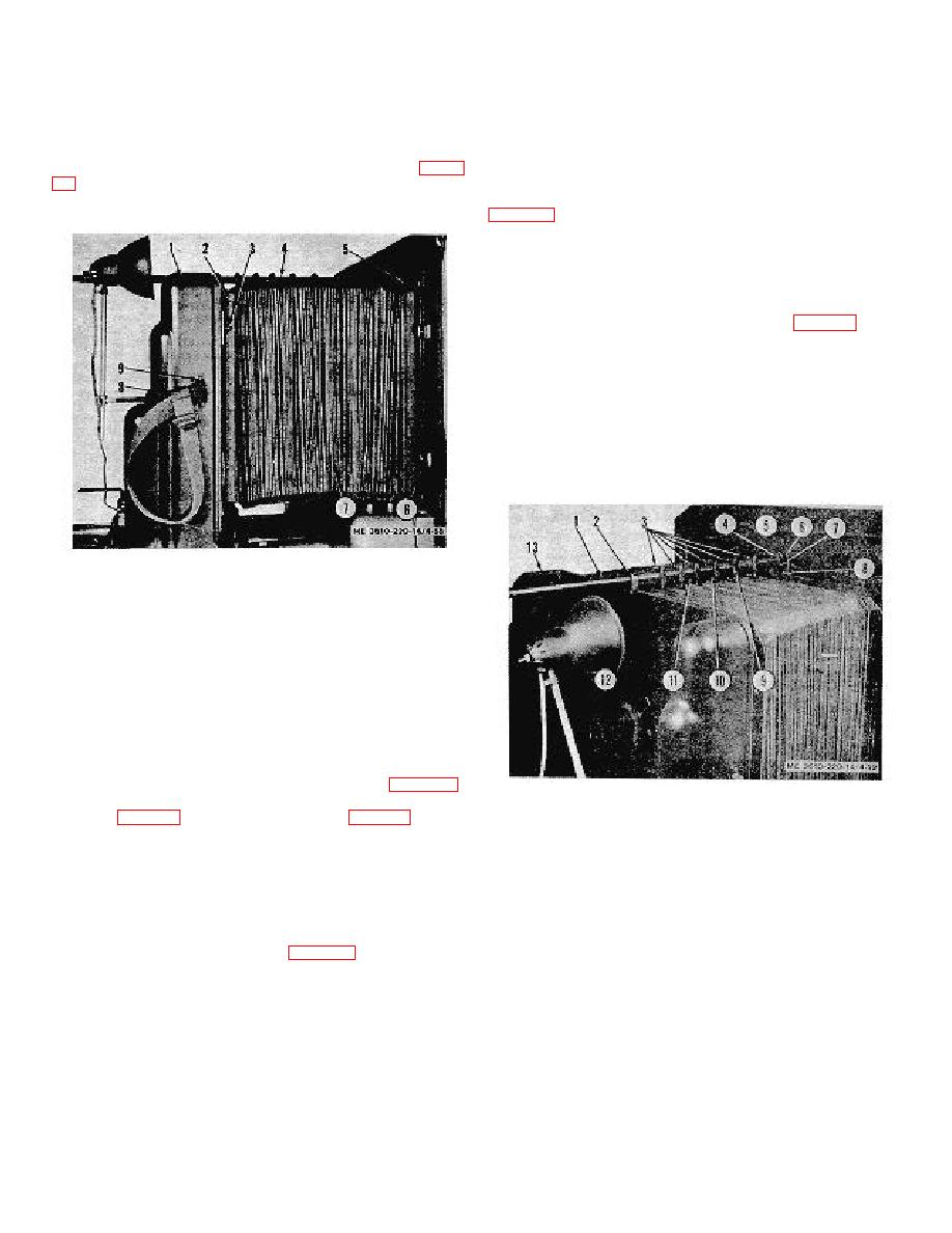
1. Lensboard
2. Bellows end frame
3. Screw, hex soc hd,
5/16-18 x 1/2
4. Tube support assembly
5. Bellows end frame
6. Clamp and screw assembly
7. Bellows
8. Bellows strap
9. Screw, hex soc hd, 3/16-16 x 3/4
Figure 4-18. Bellows assembly components.
4-36. Tube Support Assembly
1. Outer tube 2. Tube guide
consists of a pair of internally spring loaded telescoping tubes
3. Roller carrier
(3 and 5, fig. 4-20) and six roller carriers (3, fig. 4-19), and is
4. Screw, rd hd, 10-32 x 11/4
supported on the lensboard by a tube guide (2) on one end and
5. Tube flange
on the camera back by the tube flange (5) and flange plate (6)
6. Flange plate
on the other end. The roller carriers (3) are attached to the
7. Screw, hex soc hd, 8-32 x l/2
internal reinforcing frames by the adjacent plates pinned to the
8. Screw, hex soc hd 10-32 x 1/2
carriers.
9. Screw, hex soc hd 10-32 x 1 /2
10. Connector plate
b. Removal.
11. Hex nut
(1)
Remove screws (12, fig. 4-19) to release tube
12. Screw, hex soc hd l/4-20 x 3/4
guide (2).
13. Lensboard
Figure 4-19. Tube support assembly, installed.
4-21


