
(6) Loosen screws (4) on the support bracket (1) to
d. Cleaning and Inspection. Clean all parts thoroughly
release the transformer. Lift the transformer from the support
with a cleaning solvent and clean cloth.
Dry the parts
bracket.
thoroughly with a soft cloth. Inspect hinge pins (4 and 8, fig. 4-
burrs around edge of bore. Inspect threads on hingepin shafts
c. Installation.
(4 and 8), pivot pin (12), and all screws for stripped or damaged
condition. Inspect locking bracket (13) for cracks and breaks.
Replace defective parts if necessary.
(1) Replace transformer on the support bracket (1,
e. Reassembly.
(2) Be sure the transformer (2) is firmly seated, and
then tighten screws (4, fig. 4-14).
(1) Drive pivot pin (12, fig. 4-12) into free end arm
(3) Insert cable wires through transformer panel
bracket (9). Position locking bracket (13) and secure with two
and attach the locknuts (2) to connector nipples (3).
screws (16). Insert remaining screw (14).
(4) Attach loose wires to mating terminals, and
(2) Position center arm bracket (7) and hinge it to
replace the transformer cover (3, fig. 4-13).
free-end arm bracket (9) with hinge pin (8). Secure hinge pin in
position with cap nut (18) onto threaded end of hingepin (8).
f. Installation.
Position center arm bracket (7) to
secured-end arm bracket (9, fig. 4-6). Insert hinge pin (4, fig. 4-
assembly (5, fig. 4-6) with washers (8) and secure with lock nut
(7). Replace washer (8) and cap nut (10) on underside of hinge
pin (6).
4-31. Transformer
a. Description. The transformer used to supply the arc
lamps has a contactor-controlled primary input of 17 amperes
at 220 volts and a secondary output of 50 amperes at 30 to 50
volts to each lamp. The transformer (2, fig. 4-13) is located on
the copyboard end of the camera and is mounted on a bracket
(4) secured to the rear support plate (1). The transformer is
equipped with a cover (3) which, when removed, exposes the
terminal board connections and the wiring (fig. 4-14) connecting
the arc lamps and the external source cable.
b. Removal
(1) Remove the cover (3, fig. 4-13) from the
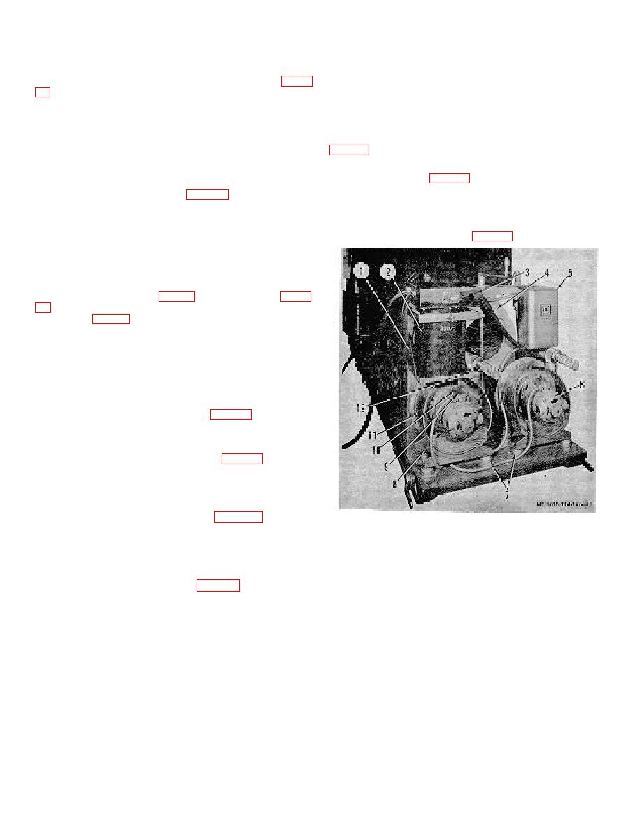
1. Support bracket
transformer (2) to make wire connections accessible.(2) Tab all
2. Transformer
wires coming from the cables using fig. i-11A for identification
3. Transformer cover
of wires and mating terminals.
4. Rear support plate
5. Magnetic contactor
(3)
Disconnect cable wires from terminals.
6. Vacuum back turbo-compressor assembly
7. Vibration mount
(4) Remove locknuts (2, fig. 4-14) from connector
8. Vibration mount nut
nipples (3). Dress wires to facilitate removing nipples.
9. Screw, rd hd, 10-32 x 3/4
(5) Remove cables from transformer, being
10. Outlet box cover
extremely careful not to snare wire insulation while pulling wires
11. Copyboard vacuum turbo-compressor assembly
through transformer panel.
12. Muffler
Figure 4-13. Camera components, copyboard end.
4-17
