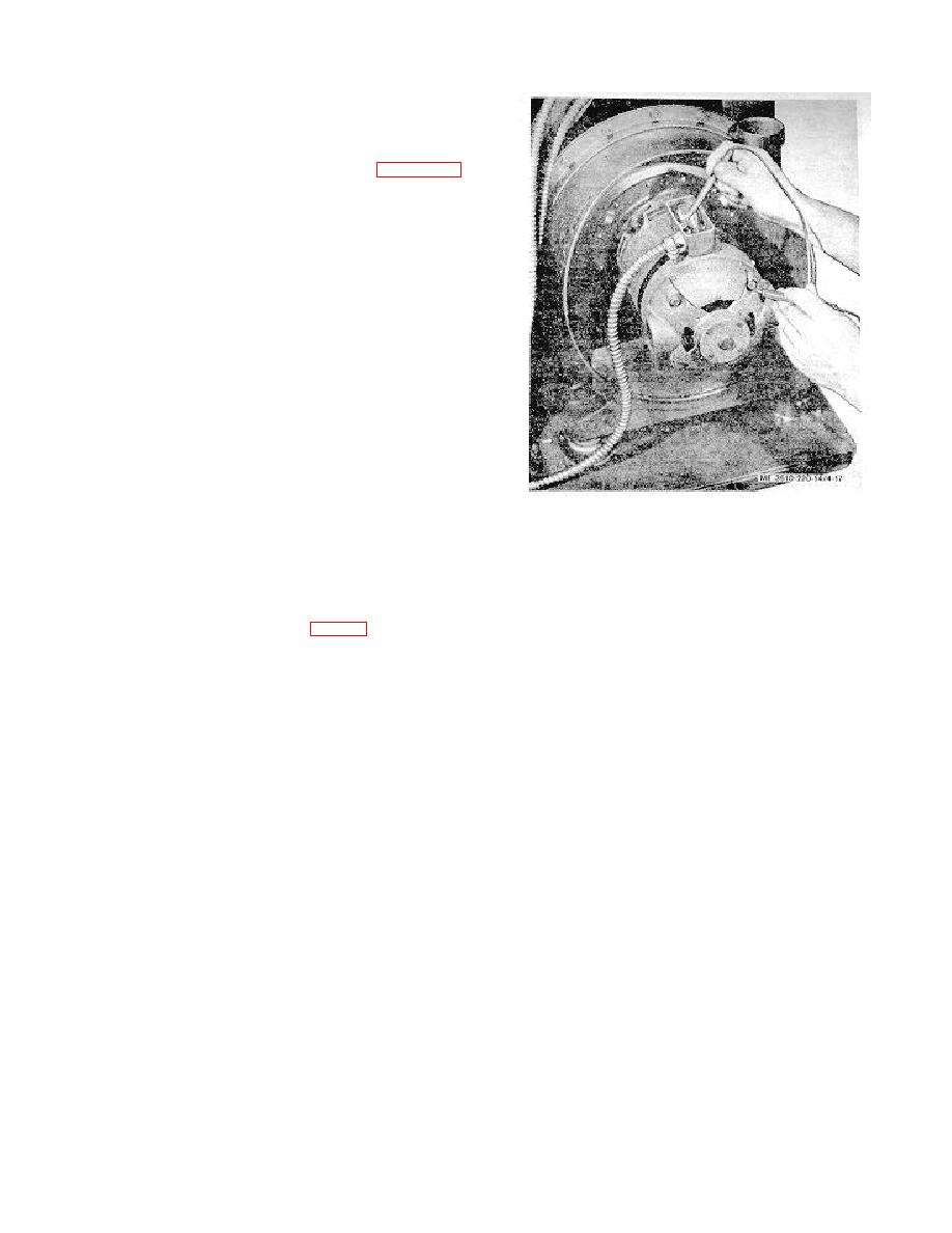
c. Testing of Short Circuit. Expose the terminal board in
outlet box of component in which shorting is occurring. Set the
switch control of the component to an ON position, theoretically
closing the circuit. Apply the test lead of test lamp to wire in
outlet box and the other test lead to the frame of component. If
shorting is present, the test lamp will not light. Figure 4-17
illustrates testing for short at turbo-compressor motor.
d. Repair and Replacement. Repair wire and cable with
electrical tape, wrapping neatly to avoid hum ping. Replace
conductors that have badly worn insulation or bare wire. Since
wires within the flexible cable are harnessed, the entire cable
must be replaced when defective conductors are present. The
wires housed inside the rigid cable are not harnessed and can
be individually replaced.
In removing short-circuited
conductors, attach new wire to defective wire on one end of
rigid cable and pull out defective wire from other end, replacing
it with a new wire. To replace broken wire in rigid cable,
remove broken segments. Wrap two new wires to end of good
wire in rigid cable. Pull this wire out from other end, replacing
the attached new wire in cable.
Figure 4-17. Testing for short circuit at turbo-
compressor motor.
Section IX. MAINTENANCE OF FOCUSING GLASS FRAME ASSEMBLY
4-34. Focusing Glass
c. Cleaning and Inspection. Clean the focusing glass with
a. Description. The focusing glass (7, fig. 2-4) is contained in
a soft, clean cloth dampened in acetone. Wipe all surfaces
the focusing glass frame by six holder clips (2 and 5) located on
thoroughly to keep focusing glass at maximum transparency.
the sides and bottom structures of the frame (4). The focusing
Dry the focusing glass with a soft, dry cloth. Clean the holder
glass is finished with a fine, uniformly grained surface which
clips with cleaning solvent and wipe parts dry with cloth.
contains a grid of photographically exposed, permanently fused
Inspect the holder clips for' bends and worn inner felt strip.
lines spaced at intervals of 0.100 inch and covering the 24by
Check clips with straight-edge forwarding. Replace defective
30-inch rated area. A clear transparent circle 1 inch in diameter
holder clip if necessary. Inspect the focusing glass for chipped
is provided in the center of the grid area on the focusing glass
edges affecting its alignment. Examine the glass for cracks and
and conforms with the optical axis of the camera.
breaks. Replace defective focusing glass.
b. Removal
d. Installation.
(1) Remove one of the bottom holder clips (2) on
(1) Install two side holder clips (5) on left side of
right side of focusing glass frame (4) by releasing four screws
focusing glass frame (4) with six screws (6).
(6).
(2) Install one bottom holder clip (2), retaining with
(2) Remove two side holder clips (5) on right side of
four screws (6). Do not tighten screw s.
focusing glass frame by removing three screws (6) on each.
(3) Position the focusing glass (7) on the focusing
(3) Supporting the focusing glass (7), loosen
glass frame under the holder clips.
screws on the remaining holder clips.
(4) Install the remaining two side holder clips (5)
(4)
Lift the focusing glass from its frame (4).
and the bottom holder clip (2) on the right side of focusing glass
(5) Release the remaining bottom holder clip and
frame. Retain with screws (6). Tighten screws on holder clips
the two side holder clips by removing screws.
previously installed.
4-20


