
4-44. Drive Motors
c. Cleaning and Inspection. Clean the outside casing of
the drive motor with a cloth dampened with cleaning solvent.
Inspect the motor for damaged casing and bent shaft. Apply a
and copyboard drive motor (20) have an electrical rating of 208
208 volt external source to motor wires and check operation.
volt, 3 phase, 60 cycle frequency.
The motors contain
Replace defective drive motor if necessary.
permanently sealed bearings requiring no lubrication.
d. Installation.
b. Removal.
(1) Position drive motor (14 or 20) on motor
(1)
Disconnect wire cable from terminal outlet box.
support bracket (17), aligning motor gear with driven gear on
(2)
Remove four nuts (19) to release drive motor
drivescrew.
(14 and 20).
(2) Retain drive motor on motor support bracket
(3) Lift the motor from the motor support bracket
with four nuts (19).
(17) being careful not to damage motor gear.
(3)
Attach wires to terminal outlet box.
Section XIII. MAINTENANCE OF TRANSPARENCY HOLDER
ASSEMBLY AND DIVERTER VALVE PLATE ASSEMBLY
4-45. Description
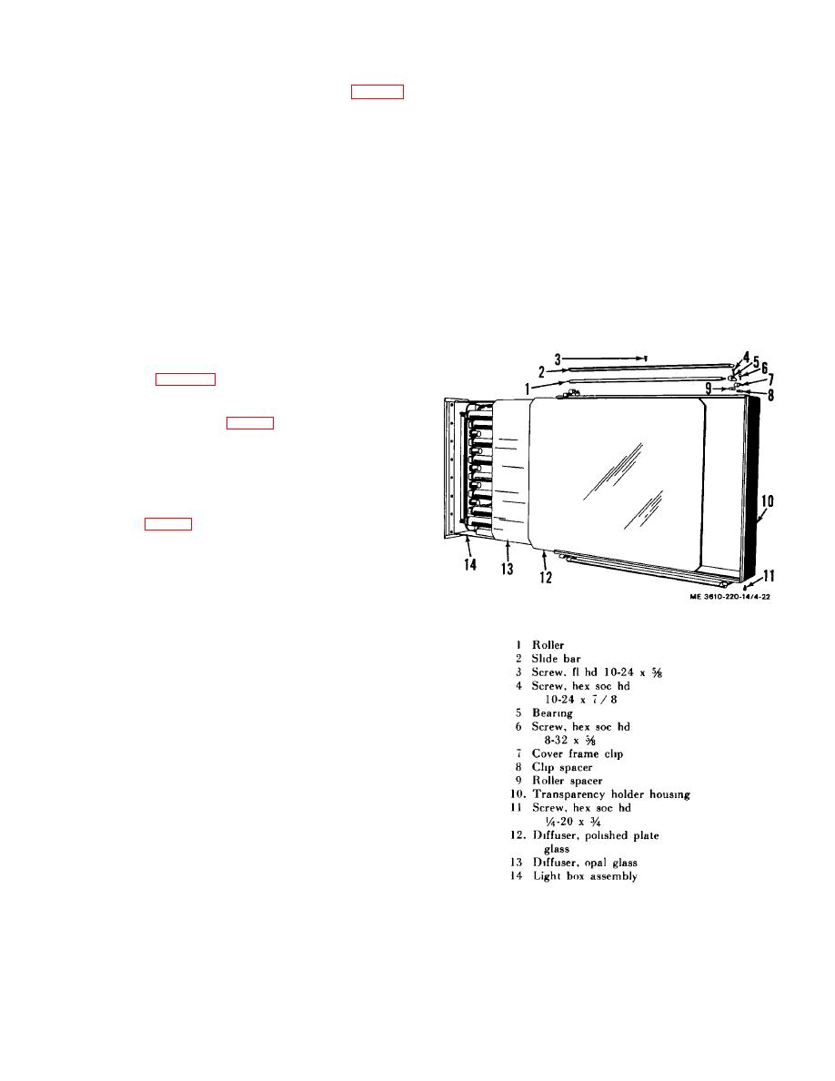
The transparency holder assembly consists of a housing light
box assembly (14, fig. 4-22), opal glass diffuser (13), and a
polished plate glass diffuser (12). The transparency holder
housing, the main structure of the assembly, is rigidly bolted to
the axle and tube assembly (3, fig. 1-6) to assure that its front
surface is of equal distance from the axis of rotation and
parallel to that of the copyboard. A diverter valve plate
assembly, secured to the transparency holder housing, controls
the suction flow through the assembly. The light box assembly,
mounted in the housing, contains fluorescent tubes to supply
the necessary illumination for copying transparencies. Mounted
on slide bars (14, fig. 1-6) on the top and bottom of the housing
are aerial film brackets (1) used to roll aerial film over the
diffuser.
Figure 4-22. Transparency holder assembly,
exploded view.
4-25
