
Section XI. MAINTENANCE OF FLASH LAMP ASSEMBLY, SHUTTER
ASSEMBLY AND LENS
4-38. Description
The flash lamp assembly, shutter assembly, and the lens listed
in this section are parts of the lensboard assembly which can be
removed and installed without affecting the calibration of the
camera. The flash lamp is located on the lensboard side frame
and is mechanically and manually operated from a pivoting
position 900 to the lens. The shutter assembly and lens are
mounted on opposite sides of the innerlensboard frame and are
optically centered with the focusing glass and copyboard. The
lens is a detachable part of the frame with its own mounting
facilities. The shutter assembly is a fixed member attached to
the frame by screws. The lens and shutter are simultaneously
adjusted through the inner lensboard frame by the lens vertical
and horizontal control knobs.
4-39. Shutter Assembly
electrically controlled standard silent shutter operating under 95
to 125 DC volts. The shutter is equipped with a power rectifier
unit for converting alternating current to direct current, and a
solenoid for controlling the shutter.
b. Removal.
(1) Remove four screws (3, fig. 4-18) to detach the
bellows (7) from the lensboard ( 1). Roll the bellows back to
make the shutter accessible.
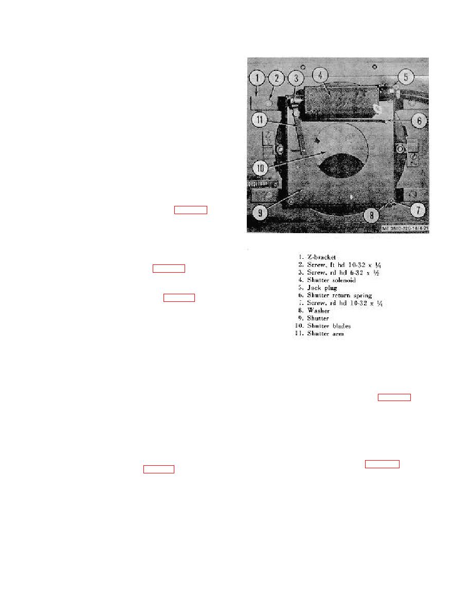
(2) Disconnect the jack plug (5, fig. 4-21) to release
the shutter (9) from the power source.
(3) Remove four screws (7) and washers (8) to
release the shutter from the two brackets (1).
c. Cleaning and Inspection. Clean the parts of the shutter
with a clean cloth. Clean the solenoid with acetone and a
separate clean cloth. Dry all parts thoroughly with tissue.
Figure 4-21. Shutter assembly.
Inspect the shutter for bends and tears. Check operation of the
shutter blades by moving shutter arm. See that blades are
4-40. Lens 19 Inch
aligned properly. Examine the solenoid for broken insulation
and loose wire leads. Replace defective parts if necessary.
d. Installation.
apochromat Artar lens equipped with an attached mounting
plate (4) and a lens cap (3). The diaphragm opening control
(1) Position the shutter (9) on the brackets and
(5), with the lens, is mounted on the lens barrel. A special lens
retain with four screws and washers (7 and 8).
box (2) is provided to store the lens when it is not installed on
(2)
Retain the solenoid cable to the shutter.
the camera.
(3 Attach
sections of jack plug (5) to connect power
b. Removal.
source.
(1) Grasp the knobs (3, fig. 2-11) on the lens
(4) Install the bellows (7, fig. 4-18) to the lensboard
mounting plate (2), and rotate 15 in a counterclockwise
( l) with four screws (3).
direction to unlock the lens (5) from the inner lensboard frame
(4).
(2) Release the lens mounting plate and the lens
from the slots of the inner lensboard frame.
4-23
