
Check the assembly for overall warping. Examine the operating
knob for satisfactory operation. If any part of the copyboard
assembly is defective, report the condition to the proper
authority.
d. Installation.
(1) Install the copyboard (1, fig. 4-27) on the axle
and tube assembly (4), being sure that it sits flush.
(2) Turn the copyboard counterclockwise so that
the locking devices (2) are inserted in the slots of the copyboard
flange. Tighten the hand knobs.
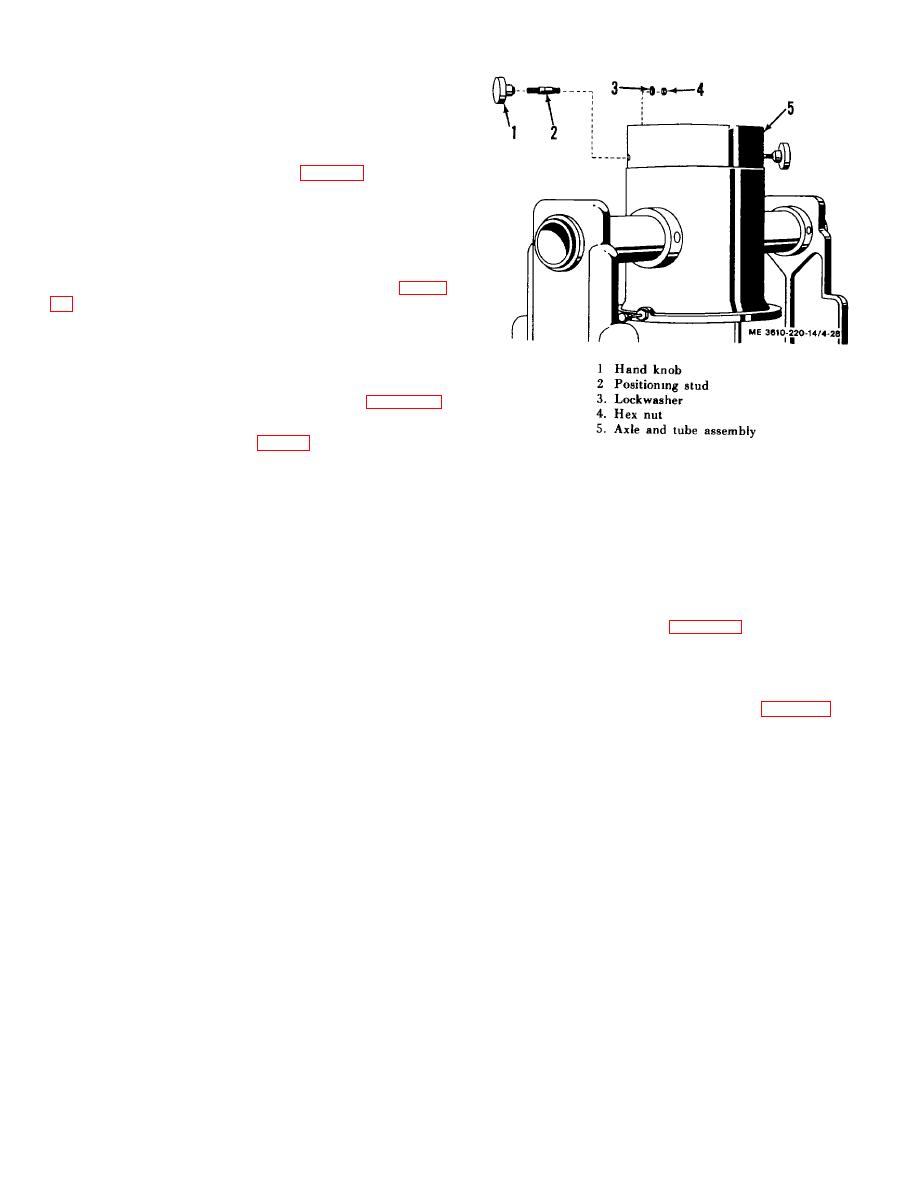
4-53. Copyboard locking Device
of a positioning stud with a hand knob threaded on the exterior
end and a lockwasher and nut on the inner end holding it to the
tube.
b. Removal.
(1)
Remove the copyboard assembly (para 4-52.
b.).
(2)
Unscrew knob (1, fig.4-28) from positioning stud
(2).
Figure 4-28. Copyboard locking device, exploded
(3) From the inside of axle and tube assembly (5),
view.
remove nut (4) and lockwasher (3) from stud (2). Tap out the
stud.
c. Cleaning and Inspection. Clean the parts with cleaning
solvent and dry with a clean, soft cloth. Inspect the hand knob
and positioning stud for worn threads, bends, and breaks.
Replace defective parts if necessary.
d. Installation.
(1) Place stud (2, fig. 4-28) in axle and tube
assembly (5). From the inside of axle and tube assembly (5),
install nut (4) and lockwasher (3) on stud (2).
(2)
Screw knob (1) on stud (2).
(3)
Install the copyboard assembly (para 4-52. d.).
4-30
