
the slide bar (2, fig. 4-22) roller (1) and bearings (5). The slide
into flange of axle and tube assembly (1). Insert stud into
bars support the aerial film brackets; the rollers guide the film
bushing and screw stop nut (8) on stud.
over the polished glass diffuser; the cover frame clips hold the
(2) Position two valve guides (5, fig. 4-25) on
cover frame secure to the housing.
transparency holder housing (6), and secure each valve guide
with two screws (7), lockwashers (4), and nuts (3). Slide
b. Removal.
diverter valve plate (2) into tracks of valve guides.
(1) Remove the aerial film brackets from the slide
(3) Position four shims (4, fig. 4-26) as marked
bar (para 4-46. b. ).
during disassembly, and secure transparency holder housing
(2) Remove four screws (4, fig. 4-22), securing two
(5) to axle and tube assembly (1) with eight screws (6),
bearings (5) to transparency holder housing (10), one at each
lockwashers (3), and nuts (2).
end of roller ( 1 ). Remove roller, bearings, and roller spacers
(4) Working through port of transparency holder
(9).
housing, slide diverter valve plate (2, fig. 425) to +he left and
(3) Remove two screws (6) from each of two cover
secure diverter plate to stud (10) with stop nut (8).
frame clips (7). Remove clips and clip spacers (8).
(5) Install the diffusers and light box assembly
(4) Remove 14 screws (3), securing slide bar (2) to
(para 4-47. d. ).
transparency holder housing (10). Lift off bar.
4-50. Aerial Film Mounting Attachments
a. Description. Two groups of aerial film mounting
attachments are provided on the transparency holder housing,
each group having identical parts. The attachments consist of
Section XIV. MAINTENANCE OF COPYBOARD ASSEMBLY AND
COPYBOARD LOCKING DEVICE
4-51. Description
The copyboard (5, fig. 1-6) is mounted on the axle and tube
assembly (3) by two hand knobs (6) which are part of the
copyboard locking devices. The locking devices fit into the slots
of the copyboard flange (4, fig. 1-6), holding the copyboard
secure. The flange is bolted to the copyboard, providing a rigid
interconnection of the assemblies.
4-52. Copyboard Assembly
a. Description.
The front surface of the copyboard
assembly contains a series of inlet holes systematically
arranged to hold copy of specified sizes. The operating knob
(7) on the back of the copyboard controls the suction area of
the assembly.
b. Removal.
(1) Loosen the two hand knobs (6, fig. 1-6) on the
axle and tube assembly (3).
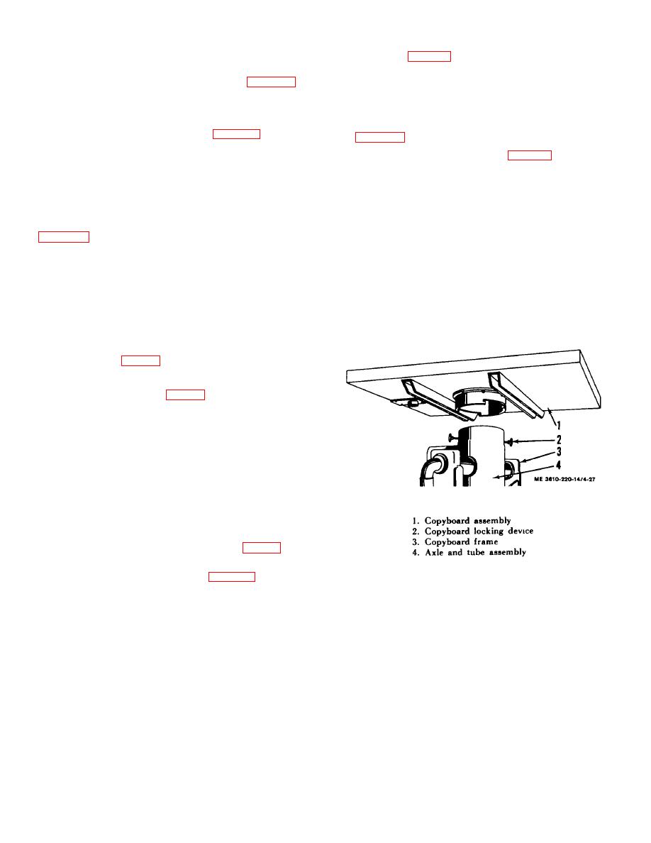
(2) Turn the copyboard (1, fig. 4-27) clockwise to
Figure 4-27. Copyboard assembly, exploded view.
free the locking devices (2) from the slots of the copyboard
flange. Lift the copyboard from the axle and tube assembly (4),
c. Cleaning and Inspection. Clean the surfaces of the
oscillating it slightly to assist its release. Be extremely careful
copyboard with a clean cloth dampened with cleaning solvent.
not to damage copyboard.
Clean clogged inlet holes on the front plate of the copyboard.
Dry surfaces thoroughly with a clean cloth. Inspect the front
plate for damaged surface, cracking, and corrosion.
4-29
