
6-31. Drive Mechanism Cleaning and Inspection
Clean all parts thoroughly with a cleaning solvent, using a small
brush to remove dirt from threaded areas. Dry parts with
compressed air. Inspect all threads for stripped or damaged
condition. Inspect gear and sprocket for chipped or broken
teeth. Inspect drivescrew bushing for scoring or wear. Replace
all defective parts.
6-32. Drive Mechanism Reassembly and Installation
a. Reassembly and Installation.
(1) Position drive screw bushing (5, fig. 6-16) and
secure with six screws (4). Slide washer (3) on drivescrew (6).
Tap key (1) into position in drivescrew (6).
(2) Position counter drive sprocket (8, fig. 6-16) on
drivescrew (6) and pin to screw with tapered pin (-11. Insert
and tighten setscrew (2). Engage counter drive chain (4, fig.
(3) Repeat the above operations on remaining drive
mechanism before proceeding further.
(4) Position shield plate (8, fig. 6-15) and secure
with two screws (hi. Position shutter switch (l O) on shield plate
and secure with two screws (13).
(5) Attach wires to shutter switch. Position cover
(11) and attach with two screws (121.
(6) Slide driven gear (14) on drivescrew (9) and
lock in place with tapered pin (6).
Position hand-vheel
extension (5) on drivescrew and secure with tapered pin (2 I.
(7) Position motor gear guard (4, fig. 6-15) on
shield plate (8) and secure with two screws (3).
Slide
handwheel (l) on handwheel extension (5) and lock with tapered
pin (2). Insert and tighten setscrew (15 }.
(8)
Repeat (6) and (1) above on remaining drive
mechanism .
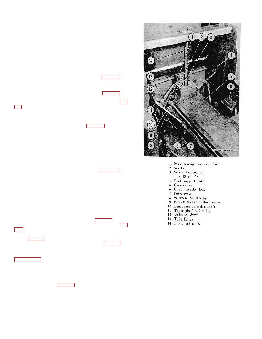
b. Adjustment. Check the end play of drivescrew at the
copyboard end of camera. See that the end of drivescrew is
resting flush in rear tube flange. To adjust, turn handwheel (7
or 9, fig. l -4 (clockwise, so as to draw carriages back and firmly
seat and take up play between sprocket (8, fig. 6-16) washer
(3), and bushing (51. Then turn take-up bushing collar (9, fig.
screw (81. Test for snug running fit by turning handwheels (7
Figure 6-17.
Camera drivescrew, showing takeup
and 9, fig. 1-4) in one direction, and then in the opposite
bushing collar,.
direction. If too tight, ease up slightly on collar (9, fig. 6-17); if
too loose, repeat adjustment operation above.
c. Calibrating. Calibrate the camera to the lens. Refer to
Section IX. MAGNETIC CONTACTOR AND ELECTRONIC SENSING DEVICES
100 percent filled, vacuum-impregnated, moistureproof type.
6-33. Description
The magnetic contactor works on 115 volt alternating current,
The magnetic contactor (fig. 6-18) is of the integral horsepower,
60 cycles. The movable
electrically-held type. A pivoting cod! arm (5) provides positive
equalized contact pressure. The magnetic coil (6) is of a solid,
6-15
