
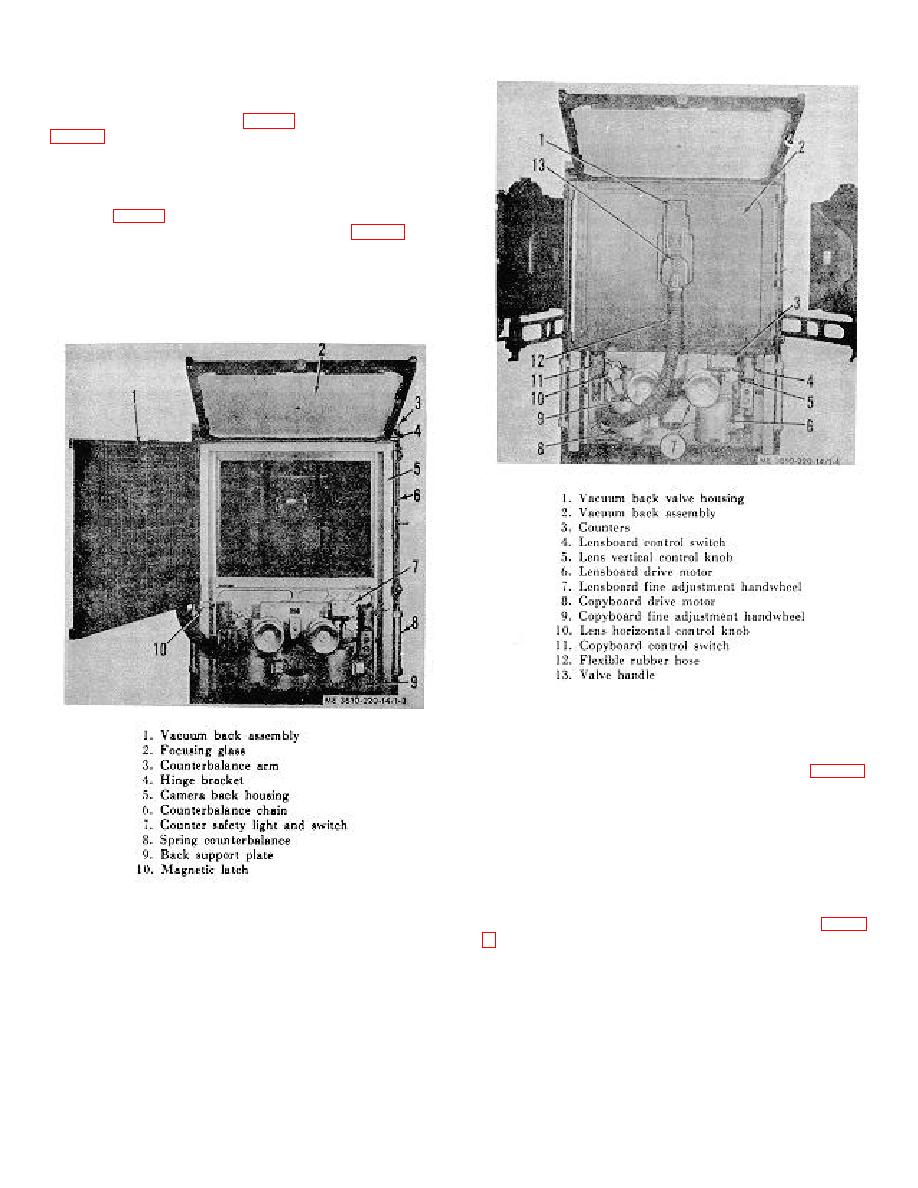
b. Camera Back Assembly. The camera back assembly
is part of the darkroom end of the copying camera, consisting
of the camera back housing (5, fig. 1-3), the focusing glass (2,
back assembly is the camera back housing, which supports
the vacuum back assembly (1) and the back support plate (9).
The back support plate is attached to the lower section of the
housing, and bears the lensboard and copyboard drive motors
(6 and 8, fig. 1-4), counters (3), and the darkroom end of the
camera drive mechanism. The focusing glass (2, fig. 1-3) and
its adjacent parts are connected to the housing by a hinge
bracket (4) and a counterbalance arm (3), one at each upper
corner of the housing frame. The side channels of the
housing secure the spring counterbalances (8) and chains (6)
of the focusing glass.
Figure 1-4. Copy camera, darkroom view with door
closed.
is hinged to and supported by the camera back housing, and
consists of a door with a porous suction plate on the inner
side and a vacuum back plate on the outer side, having
attached to it an aluminum-cast vacuum back valve housing
(1) with a valve handle (13). A flexible rubber hose (12)
extending through the back support plate is clamped to the
vacuum back valve housing.
Figure 1-3.
Copy camera, darkroom view with
vacuum back open.
the camera back (12). It is expandable and end-framed for
mounting to the adjacent components. The tube support
assembly
1-3
