
the center arm bracket (12) and the free-end arm bracket (13).
These members are adjustable to permit extending the arc
lamps to the required working distance and angle to the
copyboard so as to uniformly illuminate the copy for exposure.
1-4. Identification
The copying camera has 23 different identification and
instruction plates (fig. 1-8). The copyboard control switch and
lensboard control switch identification plates (A), both on the
darkroom end
1-6
of the camera, identifies the
manufacturer's H. P. rating and component movement. The
copyboard drive identification plate (B) and lensboard drive
identification plate (C) identifies the control switches.
Shutter switch plates (D), one on the darkroom end and one
on the lensboard side frame, locate and identify the shutter
switches. Copyboard and lensboard drive motor identification
plates (E) riveted to the motor frame designates the
manufacturer's name and other data. The rotation plates (F)
riveted to the frame of the copyboard and lensboard drive
motors, indicate direction of motor rotation. The turbine
identification plate (G) on the darkroom end identifies the
switch for the vacuum back turbo-compressor. Two arc lamp
switches identification plates (H), one on the darkroom end of
the camera and one on the side frame of the lensboard,
identify the switches. The two arc lamp switches (J) identify
the manufacturer and type. The vacuum back instruction
plate (K) on the vacuum housing sets forth the valve openings
for specified size negatives. The operating dial plate (L) on
the back of the copyboard gives instructions as to the suction
areas for specified size copy. The caution plate (M) mounted
on the copyboard frames, specifies instructions for the
transparency light box plug.
The positive holder light
identification plate (N) on the copyboard frame identifies
the light switch of the light box assembly. Manufacturer's
identification plates (P) attached to the lensboard side frame
and to the camera skid, include the model and serial number
of the camera. The caution plate (Q), mounted on top of the
cross support channel of the rear truss support assembly,
specifies instructions for the bellows and camera bed. The
caution plate (R) mounted on the rear truss assembly
specifies instructions for raising the camera. The two limit
switch identification plates (S) on the lensboard and
copyboard specifies the manufacturer's name and type. The
limit switch identification plate (T) on the lensboard identifies
the manufacturer and type. Arc lamp nameplates (U), on the
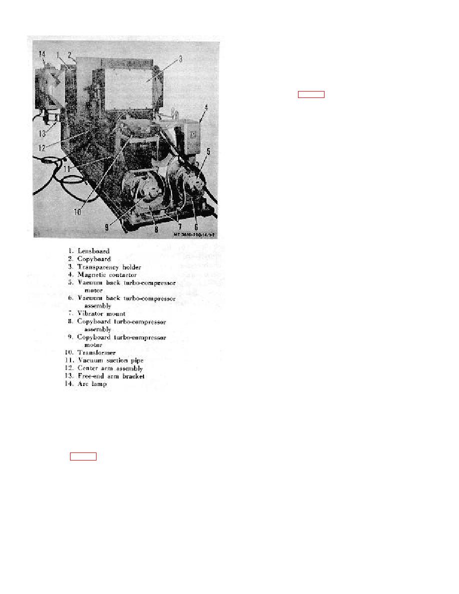
Figure 1-7. Copying camera, three-quarter view
rear panels of the arc lamps, identify the manufacturer and
type. The transformer nameplate (V), located on the
from copyboard end.
transformer side, provides the manufacturer's designation and
electrical rating. The turbo-compressor motor nameplate (W)
i. Arc Lamp Arm Assembly. There are two arc lamp
specifies the manufacturer's designation and rating. The
arm assemblies on the unit, each on opposite sides of the
turbo-compressor identification plates (X), on the compressor
camera rail and each protruding from the carriage base plate
housing, identify the manufacturer and provide electrcial and
of the copyboard. The camera arm assembly supports the
pressure data. The compressor rotation plates (Y) on the
arc lamp (14, fig. 1-7), and consists of two main structures,
compressor housing indicate rotation of motor.
1-6
