
(2) Plug in the cable connector socket 18), being
c Installation
certain that it is firmly seated in the device.
(1) Replace electronic sensing device (6) on rear
(3)
Tighten the connector nut (a) to the plug on the
truss support (9 (and attach with the four mounting screw s (5) .
device.
Section X. TRUSS SUPPORT ASSEMBLY
6-38. Description
The truss support assemblies are the legs of the camera. The
trues supports (8, fig. 1-1) on the copyboard end of the camera
skid (11) support the transformer (2, fig. 4-13) and magnetic
contactor (5) by a rear support plate (4), which serves as a
mounting base connecting the two truss supports. The truss
supports are rigidly bolted to the camera skid and are
crossmembered at the top by a support channel. The truss
support (8, fig. 1-1) on the darkroom end is similarly mounted,
with the exception that it is not equipped with a support plate
and the circuit breaker boxes (6, fig. 6-17) are mounted on each
side of the truss support.
6-39. Truss Support Removal and Disassembly
magnetic contactor (para 6-34. a. I. Set wire cables aside and
away from working area.
b.).
d. Remove cover from main junction box (8, fig. 2-53 and
disconnect wires from terminals. Remove four screws (6, fig.
filter bracket (3) with two screws (2). Release the circuit
breaker (6, fig. 6-17) by removing four screws inside of circuit
breaker box. Remove in-terlock switch (6, fig. 6-19) by
releasing two screws on the inside of truss support (S I.
truss supports (10 and 14) by removing four screws (12).
(3) to support channel (6). Lift off guard and remove bearing
(4) and bearing retainer (5) from the rear jack screw (7) and
channel (6).
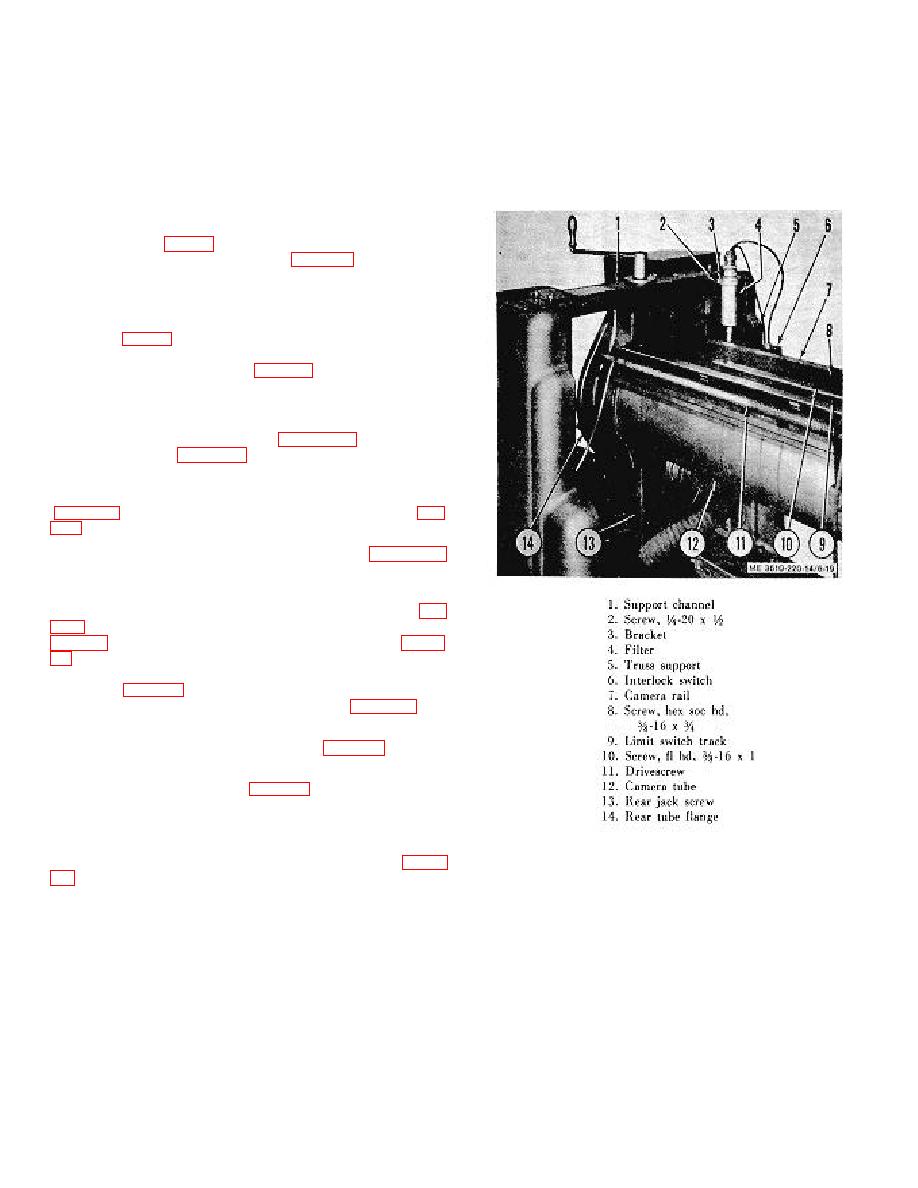
Figure 6-19.
Truss support assembly, copyboard
end.
truce support (10) from the camera skid (13). Remove trues
support (14) in similar manner. The truss supports mounted on
the darkroom end of camera are similar to this group of trues
supports. Use same procedure.
6-17
