
CHAPTER 6
REPAIR INSTRUCTIONS
Section I. VACUUM TURBO-COMPRESSOR ASSEMBLIES
6-1. Description
6-2. Vacuum Turbo-Compressor Disassembly
Two identical vacuum turbo-compressor assemblies are
a. Removal.
mounted side by side at the copyboard end of the camera. One
(1) Remove four nuts (8, fig. 4-13) securing the
vacuum turbo-compressor assembly (11, fig. 4-13) provides
vacuum turbo-compressor assembly to the vibration mount (7)
suction at the copyboard and the other vacuum turbo-
and camera skid.
compressor assembly (6) provides suction at the vacuum back.
The inlet of the turbo-compressor (11) is connected to the
(2) Disconnect wire cable from the motor outlet box
copyboard by a flexible hose (4, fig. 6-1) thus forcing all the
at main junction box.
intaken air to be drawn through the copyboard. A muffler (12,
(3) At the rear of the assembly, loosen screw (3, fig.
air. The other assembly is similarly connected to the vacuum
back of the camera. Each vacuum turbo-compressor is capable
(4)
Lift off the vacuum turbo-compressor assembly.
of drawing 75 C.F.M. of air at 16 oz P.S.I., and is driven by a 1
hp, 25 to 60 cycle AC / DC motor. Two impeller plates (20 and
22, fig. 6-2) are bolted to the motor shaft and are separated by
b. Disassembly.
a stationary disk (7). The impeller plates are spaced at least
one-eighth of an inch from the stationary disk; for this reason
(1) Unscrew compressor extension (1, fig. 62) and
there are no wearing parts, except for the motor parts. The
remove four screws (24) securing cover plate flange (2) to cover
compressor body is sealed by a heavy cover plate (4, fig. 6-2)
plate (4). Remove cover plate flange.
and cover plate ring (3), limiting the entry of air to the inlet
connection.
(2) Remove 16 nuts (16) and bolts (23), securing
cover plate (4) to turbo-compressor housing (15). Lift off cover
plate and discard gasket (5). Separate cover plate ring (3) and
cover plate.
(3) Remove two screws (6) and nuts (21), clamping
outer impeller plate (22) to motor shaft. Slide off outer impeller
plate.
(4) Remove disk ring (8, fig. 6-2) and stationary
disk (7). Remove two screws (6) and nuts (21) clamping inner
impeller plate (20) to motor shaft. Slide off inner impeller plate.
(5) Remove four screws (9) and nuts (13), securing
turbo-compressor motor (14) to turbocompressor housing (15).
Slide out motor.
(6) Remove two screws (19), securing filler plate
(18) to turbo-compressor housing (15). Lift off filler plate and
gasket (17).
(7) Unscrew muffler (12) from nipple (11), nipple
from elbow (10) and elbow from housing (15)
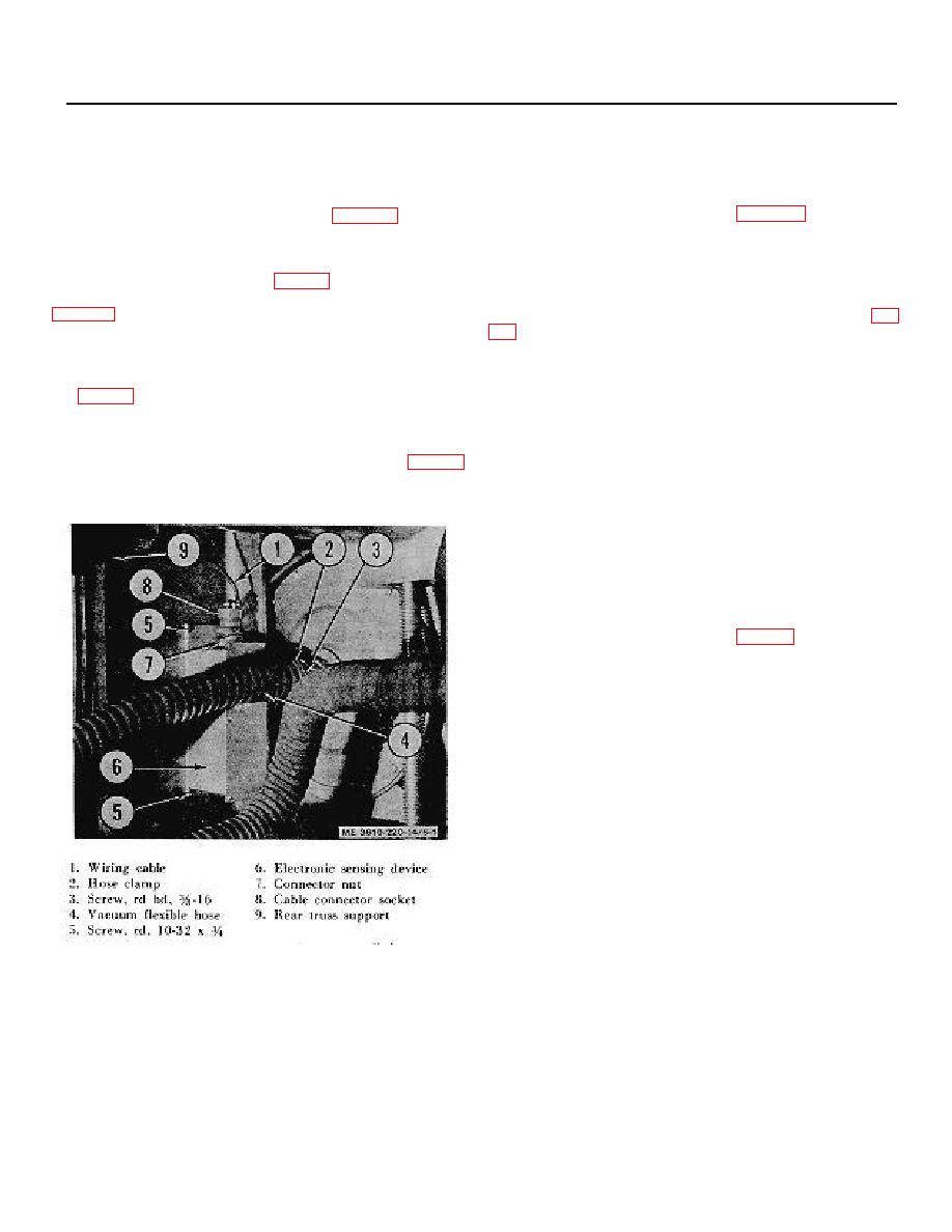
Figure 6-1. Electronic sensing device, installed.
6-1
