
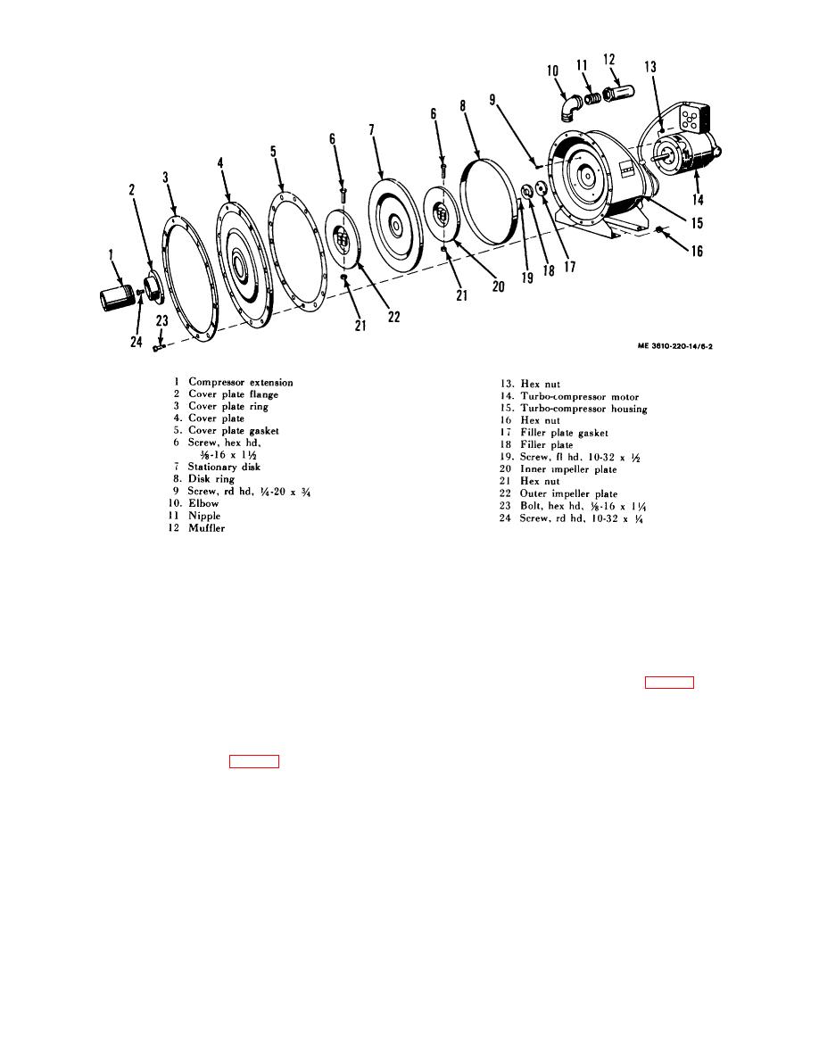
Figure 6-2. Vacuum turbo-compressor assembly, exploded view.
6-3. Vacuum Turbo-Compressor Cleaning
and Inspection
(4) Slide inner impeller plate (20) on protruding
Wash the parts of the turbo-compressor with a cleaning solvent
motor shaft and space it 0.127 plus or minus 0.002 inch from
and a clean cloth, being certain to reach threaded areas. Dry
the filler plate (18) on the turbo-compressor housing. Clamp
parts thoroughly with a clean cloth. Inspect the impeller plates,
impeller plate to shaft with two screws (6) and nuts (21).
disks, and rings for bends and distortion. Check the housing for
dents and holes. Examine the muffler for clogged filter
(5) Insert stationary disk (7, fig. 6-2) and disk ring
suppression. Replace all defective parts.
(8) into position in turbo-compressor housing (15). Slide outer
impeller plate (22) on turbo-compressor motor shaft, spacing it
6-4. Vacuum Turbo-Compressor Reassembly
0.127 plus or minus 0.002 inch from the stationary disk (7).
a. Reassembly.
Clamp impeller plate to shaft with two screws (6) and nuts (21).
(1) Screw elbow (10, fig. 6-2) and nipple (11) into
(6) Start motor with external power source and
outlet of turbo-compressor housing (15) and install muffler (12).
check impeller plate settings. Plates must rotate freely with no
binding or rubbing. Adjust impeller plate to eliminate rubbing or
(2) Position filler plate gasket (17) and secure filler
binding.
plate (18) to turbo-compressor housing (15) with two screws
(19).
(7) Position new cover plate gasket (5, fig. 62) on
turbo-compressor housing (15), and secure cover plate (4) and
(3) Position turbo-compressor motor (14) on turbo-
cover plate ring (3) to housing with 16 bolts (23) and nuts (16).
compressor housing (15) and secure with four screws (9) and
nuts (13).
(8)
Secure cover plate flange (2) to cover plate
6-2
