
6-27. Lensboard Carriage Cleaning and
Inspection
Clean all parts thoroughly with a cleaning solvent, using a small
brush to clean threaded areas. Inspect frames for splits,
cracks, and distortion. Replace if defective. Inspect carriage
base plate for cracks and splits. Inspect all threaded areas for
stripped or dam aged condition. Inspect gibe and shims for
scoring or wear and gears for damaged teeth. Replace all
defective parts.
6-28. Lensboard Carriage Reassembly
camera rail, and line up four side bearing gibe (8) and shims
(9). Secure each gib to carriage base plate with eight screws
(5, fig. 6-12). Take up play between gibe and rail, as with
copyboard carriage (para 6-20. b. (1))-. Position carriage
base plate and drive bracket (5, fig. 6-13), and secure bracket
to base plate with two screws (2).
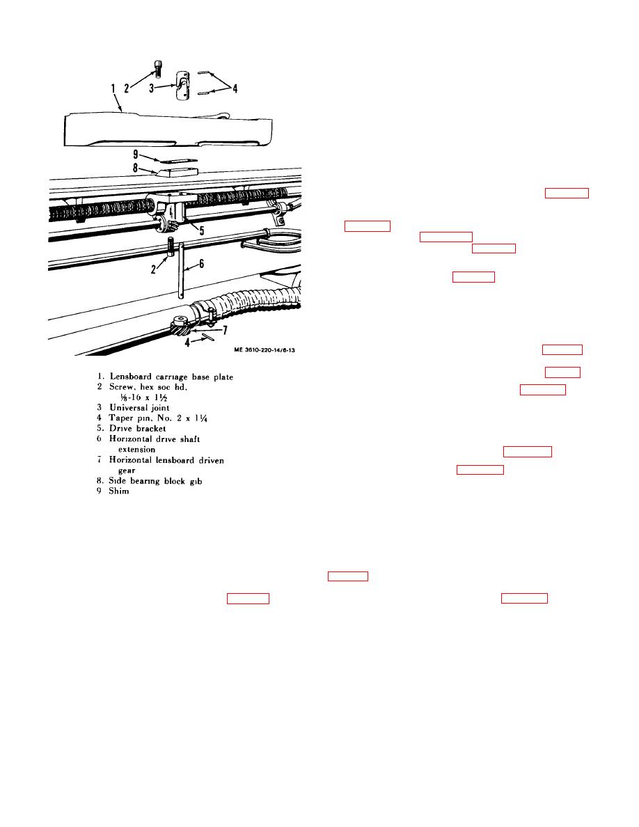
extension (6), and lock on extension with tapered pin (4). Slide
extension assembly through drive bracket (5) and base plate
(1), and attach universal joint (3) to extension with tapered pin
(4). Install vertical drive shaft extension and driven gear on
other side of base plate in the same manner.
wiper guards (14), and secure each to carriage base plate (17)
with two screws (15). Install two limit switches (10, fig. 1-5).
carriage base plate (6). Insert pins (3) and align holes. Insert
two lockwashers (1) and hex socket head screws (2), and tap
pin (3) into place. Install the side frame (a) in the same
manner.
Figure 6-13. Lensboard carriage base plate, exploded
view.
Section VIII. CAMERA DRIVE MECHANISM
pinned to the drive-screw (12 and 13). A handwheel (7 and 9,
6-29. Description
The copyboard drive mechanism and the lensboard drive
counter drive sprocket is connected to the positioning counter
mechanism are identical systems. The data in this section are
by a counter drive chain (4 and 6, fig. 6-14). The drive
applicable to either unit. A gear (1 and 10, fig. 6-14) mounted
mechanism is disassembled on its removal.
on the drive motor shaft is meshed with a gear keyed and
6-13
