(3) Center axle and tube assembly (((and slide both
axle collars (6) against frames (4). Secure collars into position
by tightening two screws (5 (in each collar.
(4) Position ring (3, fig. 6-9) on axle and screw on
cap (8). Place ring (3) and elbow assembly (1) on other end of
axle; secure elbow assembly with screw (2).
(5) Position two secured-end arm brackets (1 1)
and secure each with six screws (14).
(6)
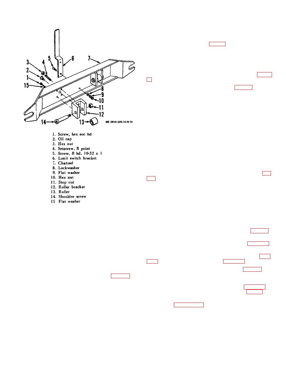
Reassemble the cross brace assembly (5, fig. 6-
8) as follows:
(a) Position roller (13, fig. 6-10) in roller
bracket (12 (and tap in shoulder screw (14). Secure screw with
a new stop nut (11) to prevent the possibility of the old stop nut
from working free from the shoulder screw and causing damage
to the base plate and camera bed.
(b) Position roller assembly in cross
brace channel (hi and secure with two set screws (4l, two nuts
(3l, two screws (1) and two flatwashers (15-. Assemble and
install remaining roller in the same manner.
(c) Install oiler (2).
(d) Position limit switch bracket (6) and
secure with screws (5l, lockwashers (8l, flat-washers (9) and
nuts (10).
b. Installation.
(1) Position copyboard carriage assembly on
camera rail and secure to four side bearing block gibe (13, fig.
gibe draw carriage snugly to rail to provide a sliding fit without
shake or play. Use shims if necessary to take up wear and
play. If wear is pronounced, also check rail for wear as setting
the gibe properly in the center of movement of the copyboard
carriage may result in binding at the extremes. Check for wear
by placing a precision straight edge on the rail. Low spots will
be visible below the straight edge, or can be determined with
Figure 6-10. Cross brace assembly, exploded view.
shims. If rail is worn, it should be scraped into a uniform and
true sliding with the carriage.
6-19. Copyboard Carriage Cleaning and Inspection
Clean all parts thoroughly with a cleaning solvent and a clean
(2) Install the cross brace assembly (5, fig. 6-8)
cloth, being certain to reach threaded areas. Examine threaded
with two hinge pin nuts (6) and washers (7).
areas for stripped and damaged condition. Inspect all parts for
(3)
Install the copyboard locking device (para 4-53.
cracked or broken condition. Check rollers, gibe, and shims for
d.1
wear and burred working surface, and the axle and tube
assembly for warping. Replace defective parts.
(4) Install the transparancy holder assembly (para
6-20. Copyboard Carriage Reassembly
(5) Replace new oil felt wiper (11, fig. 6-8) on
a. Reassembly.
copyboard carriage base plate (3) and install with wiper guards
(1) Position copyboard frame (4, fig. 6-9) on
(9) and screws (101. Lubricate all four wipers.
carriage base plate (10) and attach with four hex socket head
screws (18). Drive in two dowel pins (17).
(6) Install the arc lamp arm assembly (para 4-30.1)
and position arc lamps on free-end arm bracket (14, fig. 4-6).
(2) Slide an axle collar (6) on each end of axle but
do not tighten screws (5). Insert one end of axle into installed
c. Calibratin. Calibrate the copyboard to the lens
frame and, while supporting weight of axle and tube assembly,
as detailed in paragraph 5-6. b.
slide remaining frame into position and secure frame to carriage
base plate (10) with four hex socket head screws (181. Drive in
two dowel pins (171.
6-10


