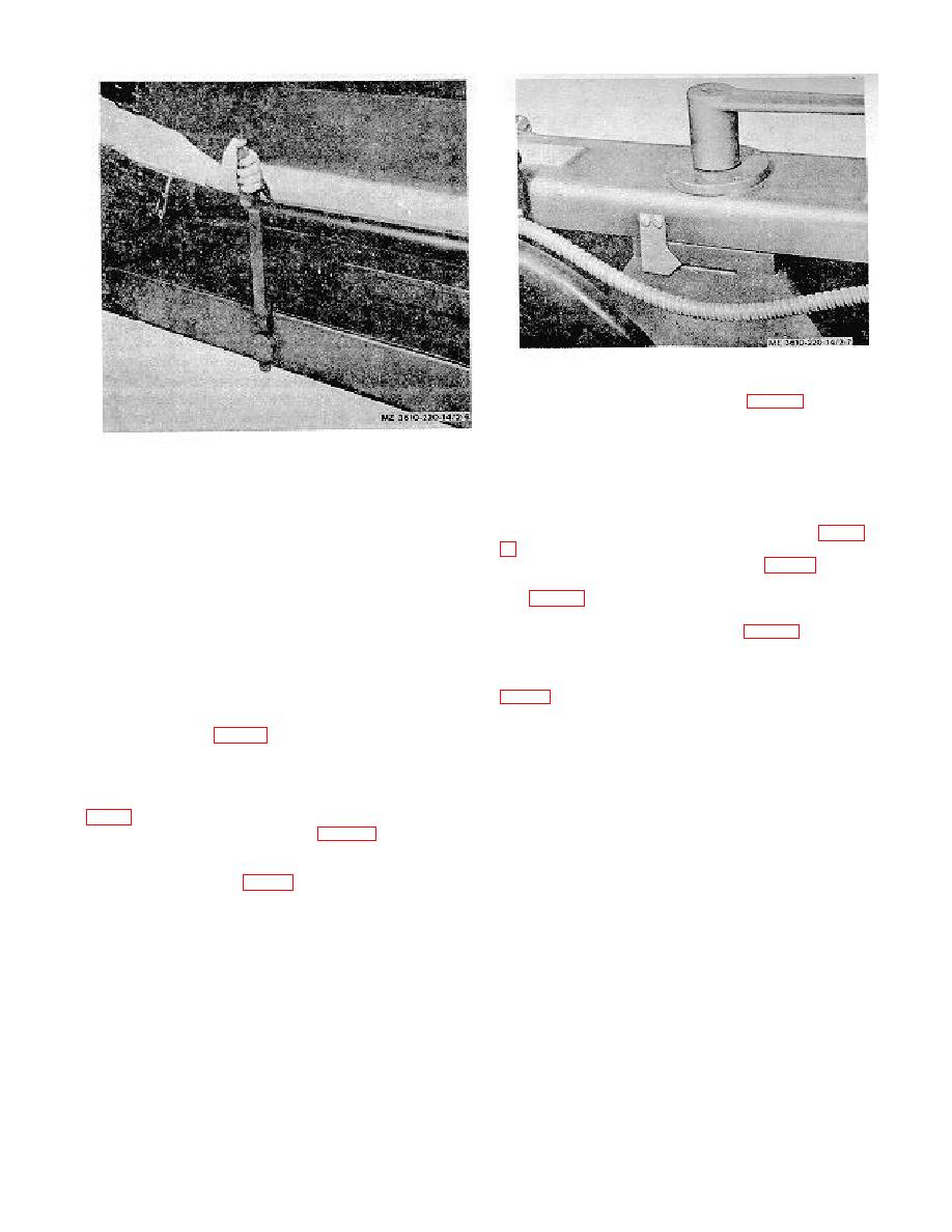
Figure 2-7. Camera at operating height.
(d) Remove the lens storage box (3, fig. 2-5) from the
lensboard carriage base plate.
(e) Open vacuum back and raise the
Figure 2-6. Retracting wheel of camera skid.
focusing glass. Loosen the locking knobs (10, fig. 25),
two on each side of the camera back. Move the hinge
(3) Power source. The camera is electrically
brackets 49) forward (toward the copyboard), and
rated as 208 volt, 3 phase, 60 cycle, 4 wire equipment,
tighten the locking knobs.
and will operate off a similarly rated portable generator
(f) Unfasten the bellows strap (2, fig. 2-
or power line supply. This fourwire system will also
supply 120 volt output between any of the phase wires
Fasten with clamp and screw (15 and 16, fig. 1-5).
and the fourth or ground wire. As some of the camera
(g) Loosen the holding stud locknuts
equipment is rated for 110 or 115 volt operation, any
(11, fig. 1-5) locking the arc lamp arm brackets to the
installation involving other than the prescribed power
lensboard carriage. Move the lensboard away from the
source must be checked with an electrician before any
copyboard by turning handwheel (7, fig. 1-4) until the
connections are made.
arm bracket disengages the holding stud. Tighten the
(4) Setting-up procedures.
locknuts to avoid losing them.
(h) Install the bottom curtain holder (9,
(a) Remove
copyboard
blocking,
release both hand knobs, rotate copyboard 90 on its
darkroom end of camera. Fasten the bottom curtain (8)
axle and tube assembly, tighten both hand knobs, and
to bottom of back support plate with thumbscrews (7).
swing copyboard (4, fig. 2-5) to a vertical plane.
Insert vertical connecting frame strip (6) so that flexible
(b) Loosen the four turnbuckles (6), and
material fastened to the camera back lies in channel
unhook them from the camera tube (7).
groove, and then assemble the strip to the bottom
(c) Raise the camera bed to operating
curtain holder with cotter pins (3). Place top curtain
height by turning the jackscrew with crank handle (7,
holder (I) on top of the vertical connecting frame strips,
and assemble with cotter pins (3). Fasten the top
the copyboard end of the camera (fig. 2-7). When the
curtain (2) to top of screen housing with thumbscrews
mark on the camera bed coincides with the pointer, the
(7). Insert darkroom panels (4) into grooves of strips to
bed is at operating height. Remove the crank handle
close balance of wall opening.
and return to toolbox (6, fig. 1-2).
2-6


