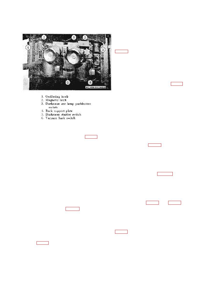
b. Location. Mounted on the side frame of the
c.
Purpose. Starts and stops operation of the turbo-
lensboard.
compressor providing vacuum to the camera back.
c. Purpose. Provides control of the shutter from
light-room end of camera.
2-23. Darkroom Arc Lamp Switch
a. Description. The darkroom arc lamp switch (3,
STOP markings.
. Location Mounted on the back support plate
of the camera back.
c. Purpose. Provides control of the arc lamps
from the darkroom end of camera.
2-24. Lensboard Arc Lamp Switch
a. Description. The lensboard arc lamp switch is a
two-element push button control (13, fig. 1-5) with OFF-
ON markings.
b. Location.
Mounted on the lensboard side
frame.
c. Purpose. Controls the arc lamps from the light
room end of the camera.
2-25. Flash Lamp Switch
a. Description. The flash lamp switch (4, fig. 15)
is a two-position rotating knob which is part of the socket
base of the lighting fixture.
b. Location. Wired directly in the flash lamp.
Figure 2-9. Darkroom controls of camera back.
c. Purpose. Provides a simple off-and-on control
of the flash lamp.
2-19. Copyboard Vacuum Operating Knob
a. Description. The operating knob (7, fig. 1-6) is a
2-26. Flash Lamp Arm Adjustment Screw
plastic hand knob provided with a suction zone indicator.
a. Description and Purpose. The flash lamp arm
b. Location. On the rear side of the copyboard.
adjustment screw (5, fig. 1-5) is a thumbscrew with a
c. Purpose. Operates internal valves to limit the
special tip equipped to hold the pivot shaft and flash
suction area to that required by the copy size.
lamp at a set position.
b. Location. Tapped into the lensboard side frame
through to the pivot shaft.
2-20. Aerial Film Bracket Crank
a. Description. A short arm hand crank (15, fig.
2-27. Flash Lamp Block Adjustment Screws
6) equipped with a stud and clutch to engage the aerial
a. Description and Purpose. The flash lamp block
film spool.
adjustment screws (6, fig. 1-5) are standard
b. Location. Revolves in the aerial film bracket (1)
thumbscrews equipped with a dog point to hold the cross
secured to the slide (14) mounted on the transparency
shaft of the lamp at a set position.
holder.
b. Location. On the joint block of the flash lamp
c. Purpose. To wind the aerial film from spool to
assembly.
spool so as to present and center the required frame
(aerial photograph) on the transparency holder.
2-28. Focusing Glass Magnetic Latches
a. Description and Purpose. The focusing glass
2-21. Darkroom Shutter Switch
a. Description. The darkroom shutter control is a
provided with the focusing glass assembly to hold it
three-way toggle switch (5, fig. 2-9) with OFF-ON
secure to the camera back during operating conditions.
markings.
b. Location. On the focusing glass frame, one at
b. Location. Mounted on the back support plate of
each lower corner.
the camera back.
c. Purpose. Provides control of the shutter from
2-29. Focusing Glass Oscillating Knob
the darkroom end of the camera.
a. Description. This control is a knurled knob (3,
2-22. Lensboard Shutter Switch
to the focusing glass.
a. Description. This control is a three-way toggle
b. Location. On the base of the focusing glass
switch (14, fig. 1-5) with OFF-ON markings on the toggle
frame.
knob.
2-10


