
TM 11-6720-242-35
4-27. Removal and Replacement of Lens-Mirror
b. Replacement.
Assembly and Recording Head Assembly
(1) Replacement of a cam-shaft assembly is essentially
the reverse of the removal procedure described in a
(fig. 3-3 (2))
above and in conjunction with the following procedures
a. Removal.
for calibrating the aec feedback potentiometer (72) and
setting the mechanical stop.
(1) Remove the cable clamps and the recording head
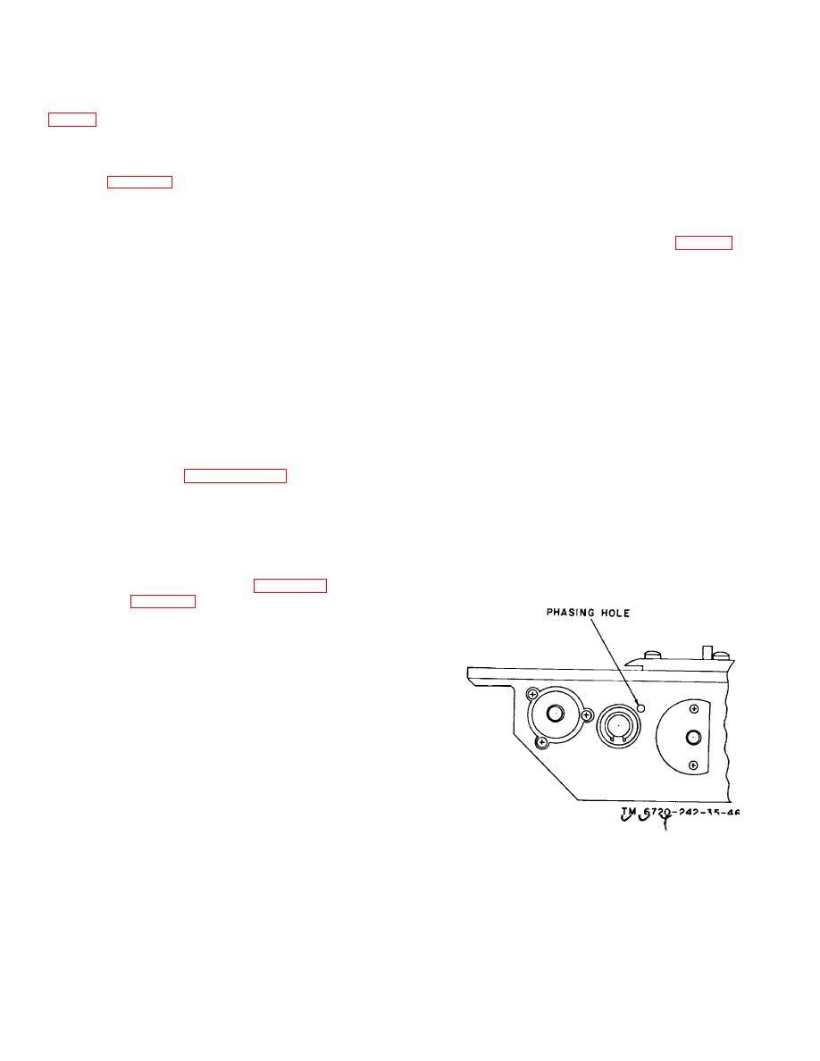
(2) When the replacement cam-shaft assembly has
assembly (para 3-15).
been installed, the stop pin (83) must be in contact with
(2) Remove the two screws (50) securing the lens-
cam stop (64) when the phasing hole in the housing
mirror assembly (49) to the housing (129). Remove the
(129) is concentric within 0.001 inch with the phasing
lens-mirror assembly (49) and the shims (51 through
hole in the cam and gear assembly (82) (fig. 4-12).
54).
b. Replacement.
(3) The calibration of the installed aec feedback
potentiometer (72) is the final step of the replacement
(1) Install a lens-mirror assembly (49) in the reverse
procedures and it is performed as described below.
sequence of the removal procedures (a above) and
(a) Procure an electrical connector MS18177 (1J3)
aline the position of the lens-mirror assembly as
which will mate with the aec harness connector 1J3 (68).
described in (2) below.
(b) Connect the required power sources and test
(2) Use the shims (51 through 54), as required to aline
switches to the leads from test connector 1J3, as shown
the circular mounting hole in the lens-mirror assembly
in figure 4-13.
(49) into which the recording head assembly is inserted,
(c) Install an index pin between the motor 'gear (47) and
with the circular hole of the housing which similarly
the gear of the cam and gear assembly (82).
supports the opposite end of the crt.
Measured
(d) Apply 7.0+0.05 volts dc across pins C and D
vertically, the center of the housing opening and the
(ground) and connect a dc voltmeter to pins B and D.
center of the lens-mirror assembly opening must not
(e) Then rotate the potentiometer shaft to obtain a
vary more than 0.007 inch.
reading of 1.04+0.02 volts on the voltmeter. Remove
(3) Install the rha assembly and the holding and cable
the index pin.
clamps as described in paragraph 3-15.
(f) Using an optical comparator for measurement,
4-28. Removal and Replacement of Cam Shaft
manually adjust the width of the slit opening
Assembly
successively to the values listed below by rotating the
gear of the cam and gear assembly (82). Check for the
(fig. 33)
voltages indicated by connecting the voltmeter across
a. Removal.
pins B and D (ground).
(1) Remove the capping blade (para 4-25) and the
shutter blade (para 4-26).
(2) Remove the screw (56), saddle washer (57) and the
cable clamp (58).
(3) Release the three screws (74) and rotate the clamps
(73) out of the slot in the potentiometer (72).
(4) Open the coils of the coupling spring (75) by rotating
both ends toward each other and withdrawing the
potentiometer shaft from the spring coupling.
(5) Remove the two screws (65) securing the cam stop
(64) to the housing (129).
(6) Remove the pin (83) securing the cam and gear
assembly (82) to the cam shaft (81).
(7) Remove the two retaining rings (76).
One is located on the outer end of the cam shaft (81)
and the other, with the spacers (77-79) and the ball
bearing (80), inside the housing (129).
(8) Slide out the cam shaft (81) through the cam and
Figure 4-12. Location of camera body phasing hole.
gear assembly (82).
4-18
