TM 11-6720-242-35
(1) Adjust the power supply for an input of 0.40 0.004
volt dc across pins 1E and 2H (signal ground)
(2) Adjust the motor load for a reading of 0.24+ 0.02
amperes on the ammeter. Check the counter for a
motor speed of 1000+40 rpm.
(3) Increase the motor load for a reading of 0.56 0.04
ampere.
(4) Adjust the scan board assembly potentiometer R22
so that the change in speed for the change in motor load
(step (3) above) is 22+4 rpm.
(5) Connect the oscilloscope to pins 1M and 2 (signal
ground). With the motor load at 0.24 0.02 ampere,
the voltage of the oscilloscope display should go
negative.
d. Linearity Test.
(1) Adjust the power supply for an input of 0.40 0.004
volt across pins 1E and 2H (signal ground). Then adjust
the motor load for a reading of 0.24+0.02 ampere.
(2) Maintain the motor load torque set in step (1) above
and perform the linearity checks of the following list.
Adjust the power supply successively for the input
voltages listed and then check the motor speed for the
rpm indicated for each voltage input.
Input voltage
Motor peed (rpm)
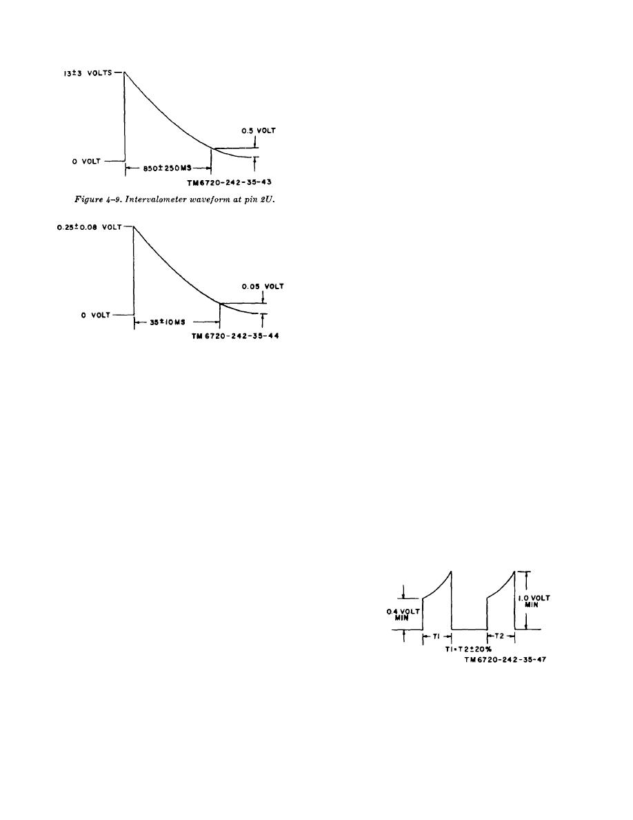
Figure 4-10. Intervalometer waveform at pin 2X.
Pit 1E-Pin 1H
Min.
Max
4-9. Testing Scan Board Assembly
0.400 0.001
970
1,030
0.800 0.002
1,940
2,060
Insert the scan board assembly into the connector of the
1.600 0.004
3,880
4,120
test fixture shown in figure 4-4.
3.200 0.008
7,680
8,240
4.800 0.012
11,640
12,360
NOTE
When the designated value or
(3) If there is a variation in the linearity at low speeds
condition of a test is not obtained,
(input voltages of 0.400 and 0.800 volt) replace resistor
remove the scan board assembly
R33 with one just above or below the 33 K ohm value
from the test fixture and trace the
until the indicated motor speeds are obtained.
malfunctioning circuit is figure 6-16
e. Dynamic Brake Transistor Test. Connect pin 2E to
to isolate the faulty part or assembly
ground. Set test switch S2 so it will connect -15 vdc to
for replacement.
pin 2J. Connect the voltmeter across pin 2J and pin 1C
and check for a reading that is between zero and -3.2
a. Preliminary Procedure. Set scan board assembly
vdc.
potentiometer R20, 20 turns counterclockwise before the
power is connected, Set test switch S1 to on.
b. Balance Adjust.
(1) Adjust the power supply for an input of 0.8+0.01 volt
dc across pin 1E and pin 2H (signal ground)
(2)
Place test switch S3 to connect the motor
tachometer assembly to 2J.
(3)
Adjust the test set motor-tachometer brake
arrangement to obtain a motor load current reading on
the test ammeter of 0.33+0.06 amperes.
Figure 4-11. Pulse width balance waveform.
(4) Connect the oscilloscope to pins 1Z and 1C (ground).
Adjust the scan board assembly potentiometer R25 to
obtain the same waveform pulse width as shown in
figure 4-11.
c. Gain Adjust.
4-14


