
TM 11-6720-242-35
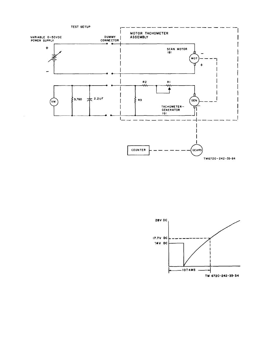
Figure 4-5. Tachometer-generator calibration, test setup.
c. Testing 115 VAC and 28 VDC Indicator Circuits. Set
(3) Set test switch S5 to on and check the oscilloscope
presentation for an annotation pulse waveform that
test switch S1 to on. All other test set switches to off.
conforms to that shown in figure 4-8.
(1) Connect the voltmeter across pin 7 and pin 5 and
check for a reading of 41.0 volts dc.
4-7. Testing AEC Board Assembly
(2) Reconnect the voltmeter across pin 2 and pin 5 and
check for a reading of 13.51.5 volts dc.
(3) Set test switch S1 to off.
Insert the aec board assembly in the connector of
d. Testing Extra Picture Circuit. Set test switch S1 to
special test fixture shown in figure 4-2.
on. All other test set switches off.
(1) Connect the voltmeter across pin 10 and pin 5 and
check for a reading of 14 1.5 volts dc.
Disconnect the voltmeter.
(2) Connect the oscilloscope across pin 22 and pin 5.
Set test switch S2 to pulse and check the oscilloscope
presentation for a waveform that conforms to that shown
in figure 4-6.
(3) Set test switch S1 to off.
e. Testing Frames Remaining, Data Annotation, and
Cycle Indicator Circuits. Set test switch S1 to on. All
other test switches off. Connect the oscilloscope to pin
3 and pin 5.
(1) Set test switch S5 to on and check the oscilloscope
Figure 4-6. Extra picture circuit waveform.
presentation for frames remaining and cycle indicator
waveform that conforms to that shown in figure 4-7. Set
S5 to off.
4-10
