TM 11-6720-242-35
will be most effective in the adjustment of the lower
output voltages, R13 of the higher voltages, and R14 of
the midrange voltages. Make the adjustments as
follows, and in the sequence the values are listed.
(6) Connect the voltmeter across pin 2N and pin 1A
(signal ground). Adjust the test fixture power source
connected to pins 2N and 1A until the given input
voltage value is read on the voltmeter. Reconnect the
voltmeter to pin 1P. The connection to 1A remains.
Then adjust R13, R14, R15 to obtain the given output
voltage value for the input voltage being applied.
Input volts
Output volts
pin 2N-1A
pins 1P-1A
0.4 0.004
4.90 0.25
0.8 0.008
5.80 0.25
1.2 0.01
6.33 0.25
1.6 0.01
6.70 0.25
2.0 0.02
6.99 0.25
3.2 0.03
7.60 0.25
4.8 0.04
8.13 0.25
c. Testing Photocell Amplifier.
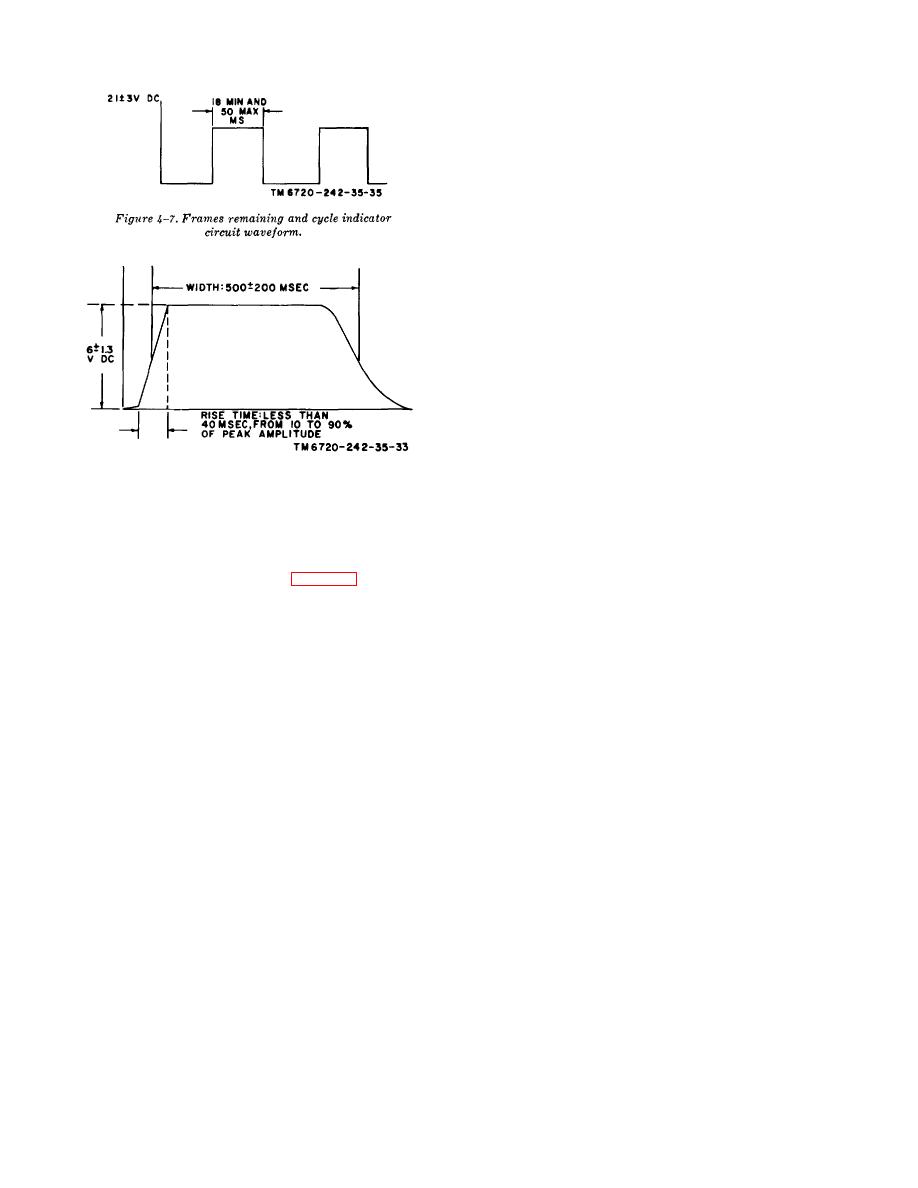
Figure 4-8. Annotation pulse waveform.
(1) Connect the voltmeter across pin 1V and pin 1A and
check for a reading of 1.0 0.02 volt.
NOTE
(2) Connect the voltmeter across pin 2L and pin 1A.
When the designated value or condition
Adjust the test potentiometer R, successively for the
of a test is not obtained, remove the aec
values in the following list and check the voltmeter for
board from the test fixture, then trace
the indicated voltage readings.
the malfunctioning circuit (fig. 6-15) to
isolate the faulty part or assembly for
Output voltage 0.2 vdc
replacement.
Rx
Pin 2L-Pin 1A
9.0K ohms 1%
10.0
a. Reference Voltage Adjustments.
6.3K ohms 1%
7.3
(1) Adjust potentiometer R8 on the aec board assembly
2.7K ohms 1%
3.7
to obtain a reading of +7.0 0.05 volts across pins 1D
and 1A.
d. Testing AEC Amplifier for Gain and Maximum Drive.
(2)
Adjust potentiometer R21 on the aec board
assembly to obtain a reading of -7.55 0.05 volts
(1) Connect the voltmeter across pins 2N and 1A and
across pin 1S and pin 1A.
adjust the test fixture 0-10 vdc power supply for a
b. Log Amplifier Calibration.
reading of +0.40 0.01 vdc.
(1) Adjust test potentiometer R. for an output of 6.3K
(2) Adjust the test potentiometer connected to pin 1T to
hms, + 5 percent, measured across 2L and 2D.
obtain a reading of -6.9 0.1vdc across pins 1T and 1A.
(2) Adjust the test 2K potentiometer connected to pin
(3) Connect the voltmeter to pins 2L and 1A and adjust
1T to obtain a reading of -6.0 0.1 volt across pin 1T
the test potentiometer R. to obtain a reading of + 4.0
and pin 1A.
0.1 vdc.
(3) Set potentiometers R13, R14, and R15 on the aec
(4) Connect the voltmeter across pins 1E and 1F
board assembly at the approximate center of their travel
(neither pin grounded) and adjust the voltage input to
(10 turns from either travel limit).
pin 2K to obtain a reading of 0 (zero) 0.5 volt rms.
(4) Measure across resistor R3 for a rating of 163
This will null the motor and cause it to stop.
ohms.
(5) Connect the voltmeter across pins 2K and 1A and
(5) Obtain the output voltages designated in the
check for a reading that must be +2.0 0.7 vdc. Record
following list for the indicated input voltages by adjusting
the voltage reading.
potentiometers R13, R14, and R15, coordinately. R15
4-11


