
TM 11-6720-242-35
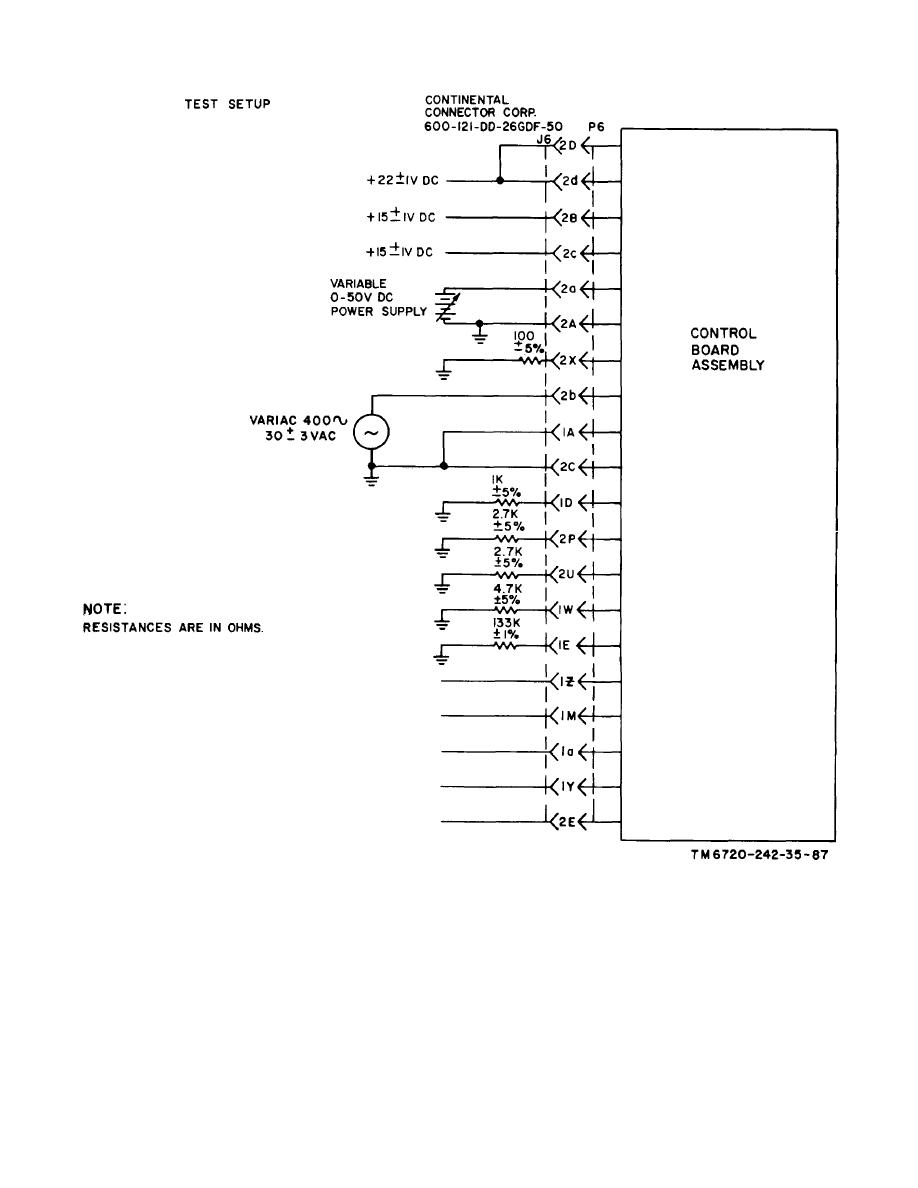
Figure 4-3. Control board assembly, test setup.
b. Testing Fail Safe Circuit. Set the test switches to the
check for a reading of 2.1 0.7 volts dc.
(2) Reconnect the voltmeter across pin 3 and pin 5 and
following initial positions:
check for a reading that is less than 1.0 volt dc. Set test
S1 to on.
switch S4 to on. The voltmeter reading must remain
S2 to off.
less than 1.0 volt dc.
S3 to off.
(3) Set test switches S1 and S4 to off.
S4 to off.
S5 to off.
(1) Connect the voltmeter across pin 25 and pin 5 and
4-8
