through the hole at the end of the projector base and the channel,
and replace the nut on the shaft from inside the channel.
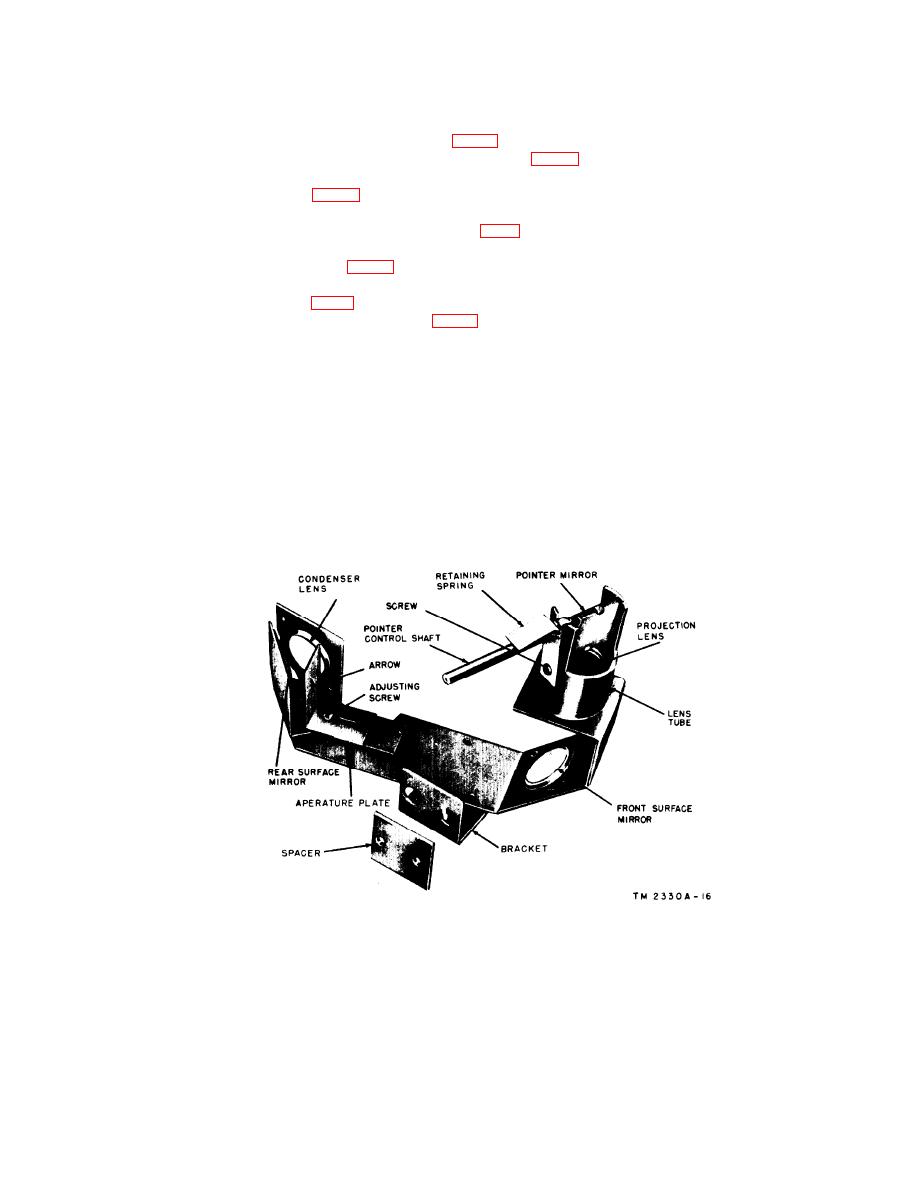
(1) To remove the pointer assembly (fig. 16) from the projector
housing, first loosen the set screw on the pointer control knob
and the hinged light shield.
(2) Remove the two screws (fig. 4) located on the side of the
projector and the nut plate from inside. A rectangular spacer
plate (fig. 16) is located between the assembly bracket and
the housing. Remove the pointer assembly and the plate
(3) Remove the screw (fig. 16) that holds the retaining spring to
the lens tube and remove the control shaft, spring, and
front surface mirror. The front surface mirror can be removed
by straightening the top retaining ear.
(4) Remove the lens from the lens tube by pushing upward from
the bottom. The lens retaining ring will slide upward with
the lens.
(5) Remove the arrow aperture plate by removing the screw that
holds the plate to the bracket.
(6) To replace the optical pointer parts and assembly, reverse
the disassembly instructions in subparagraphs (1) through
(5) above. When the pointer control knob is replaced,
tighten the set screw to the flat land on the Control knob shaft.
Figure 16. Optical pointer assembly and spacer.
43
;


