
and loosen the other six screws (fig. 13) that hold the rack
assembly. Remove the panel.
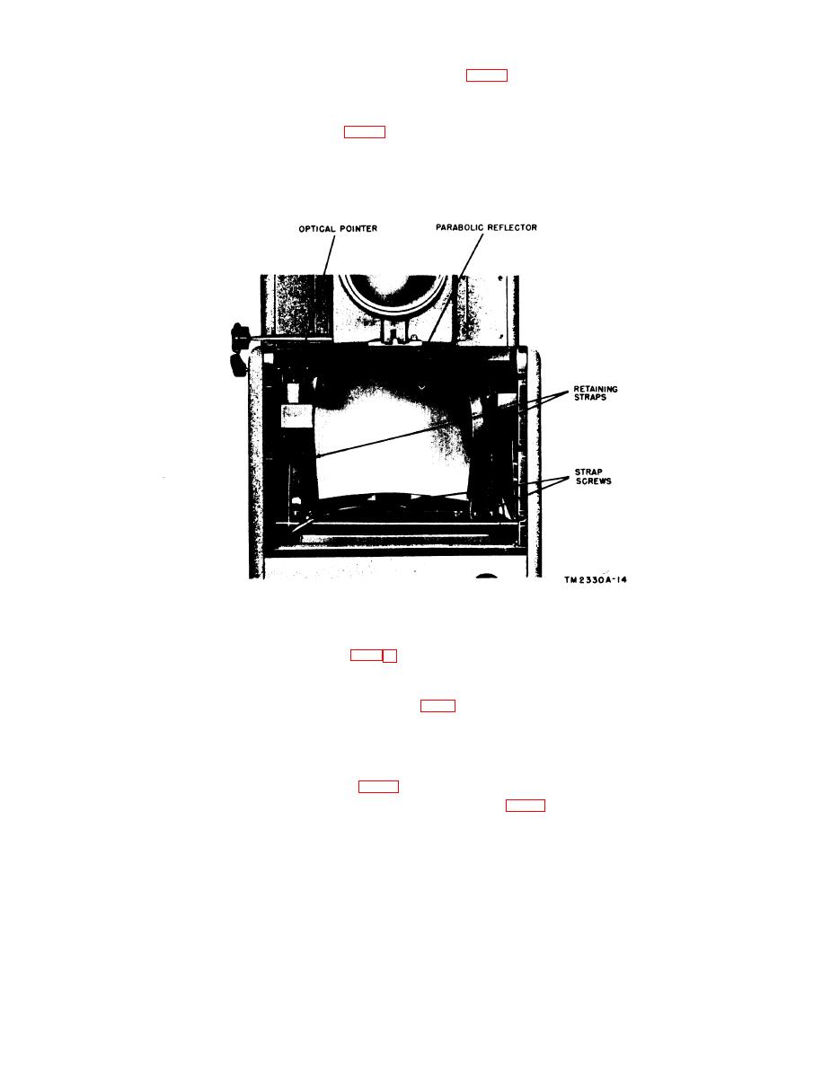
(3)
Remove the two screws that hold the reflector retaining straps
to the frame (fig. 14) , and spring lhese straps back. Carefully
lift the reflector out of the frame.
(4)
To replace the reflector, reverse the disassembly instructions
given in subparagraphs (1) through (3) above.
Figure 14. Front panel removed.
(1) To remove the door, first loosen the two knurled captive
screws that hold the door closed, and swing it open. Then
remove the four screws (fig. 5) and speed nuts that hold the
door and hinges to the projector housing.
(2) To replace the side access door, reverse the disassembly in-
structions given in subparagraph (1) above.
e. Secondary Mirrors (figs. 4 and 15) .
(I) To remove the three secondary mirrors (fig. 15), first open the
39
