TM 5-3610-220-14
Section VI. MAINTENANCE OF CONTROLS AND INSTRUMENTS
4-10. General
The various controls and instruments of the camera become
defective because of constant handling during operation,
atmospheric conditions causing corrosion and deterioration,
and general breakage of parts.
New or reconditioned
replacement parts must be exact in physical appearance and
function to maintain maximum performance of the equipment.
Under no circumstance should substitutions of components
be made unless authority comes from the proper source.
Replacement of controls and instruments involving wiring
must be handled with care to avoid strain on wire and
insulation.
4-11. Lensboard and Copyboard Positioning Counters
a. Darkroom Side.
(1)
Removal.
(a) Record
the
distance
reading
of
counters.
Note. Prior to any removal procedures, the
distance of the lensboard and copyboard, as shown on the
counters, must be recorded so that new counters may be
calibrated to identical reading. Failure to record the distances
will affect calibration of the camera.
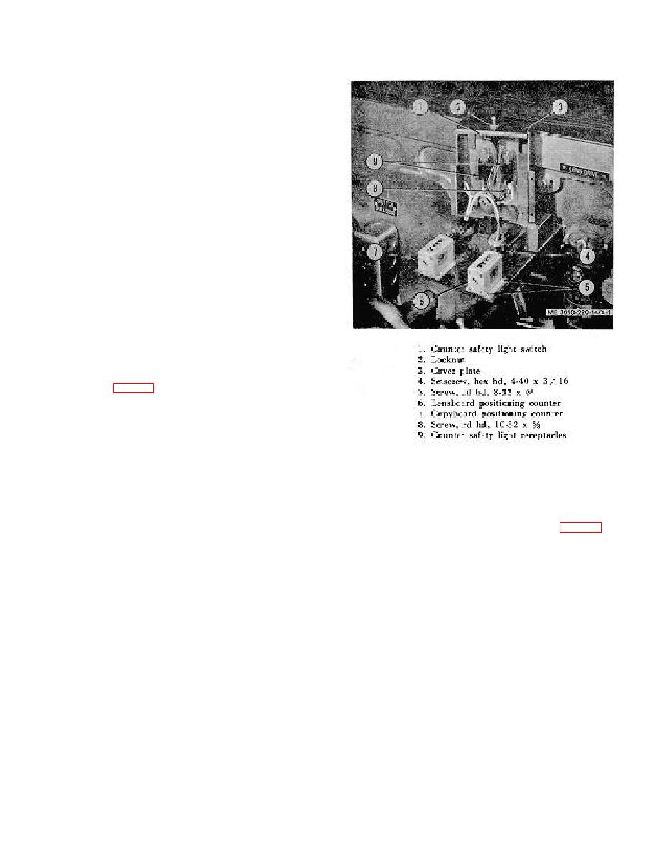
(b) Remove four screws to release the
cover plate (3, fig. 4-1) from the counters (6 and 7).
Disconnect counter safety light wires from terminals to free
cover plate.
(c) Loosen two setscrews (4) to release the
counter from the counter drive.
Figure 4-1. Positioning counters, installed,
(d) Remove four mounting screws (5), and
darkroom side.
remove the counter from its base.
(2)
Installation.
4-12.
Lensboard and Copyboard Fine Adjustment
Handwheels
(a) Set the new counter to the distance
reading.
(b) Install counter on the base, being
necessary, to make pin accessible. Tap pin through shaft
careful not to disturb digits, and tighten the two setscrews (4).
extension and handwheel. Slide the handwheel off the
extension.
(c) Fasten
counter
securely
with
four
mounting screws (5).
b. Installation. Install the handwheel on the extension,
aligning pin holes. Insert pin into hole and tap into place.
(d) Attach loose wire leads to terminals.
(e) Replace cover plate (3) with four
screws.
4-5


