TM 5-3610-220-14
4-23. Focusing Glass Oscillating Knob
b. Installation. Connect loose wires protruding from
nipple (5) to terminals of arc lamp switch (4). Attach the
switch to the nipple (5) with locknut (6). Mount switch with two
a. Removal. Lower focusing glass to an operating
screws. Slide cover plate over switch and return with screw
position, and tap out pin holding the oscillating knob (4, fig. 4-
(7).
b. Installation. Position the oscillating knob (4) on the
4-22. Flash Lamp Switch
pinion shaft, aligning the pin holes. Insert pin and tap in
place.
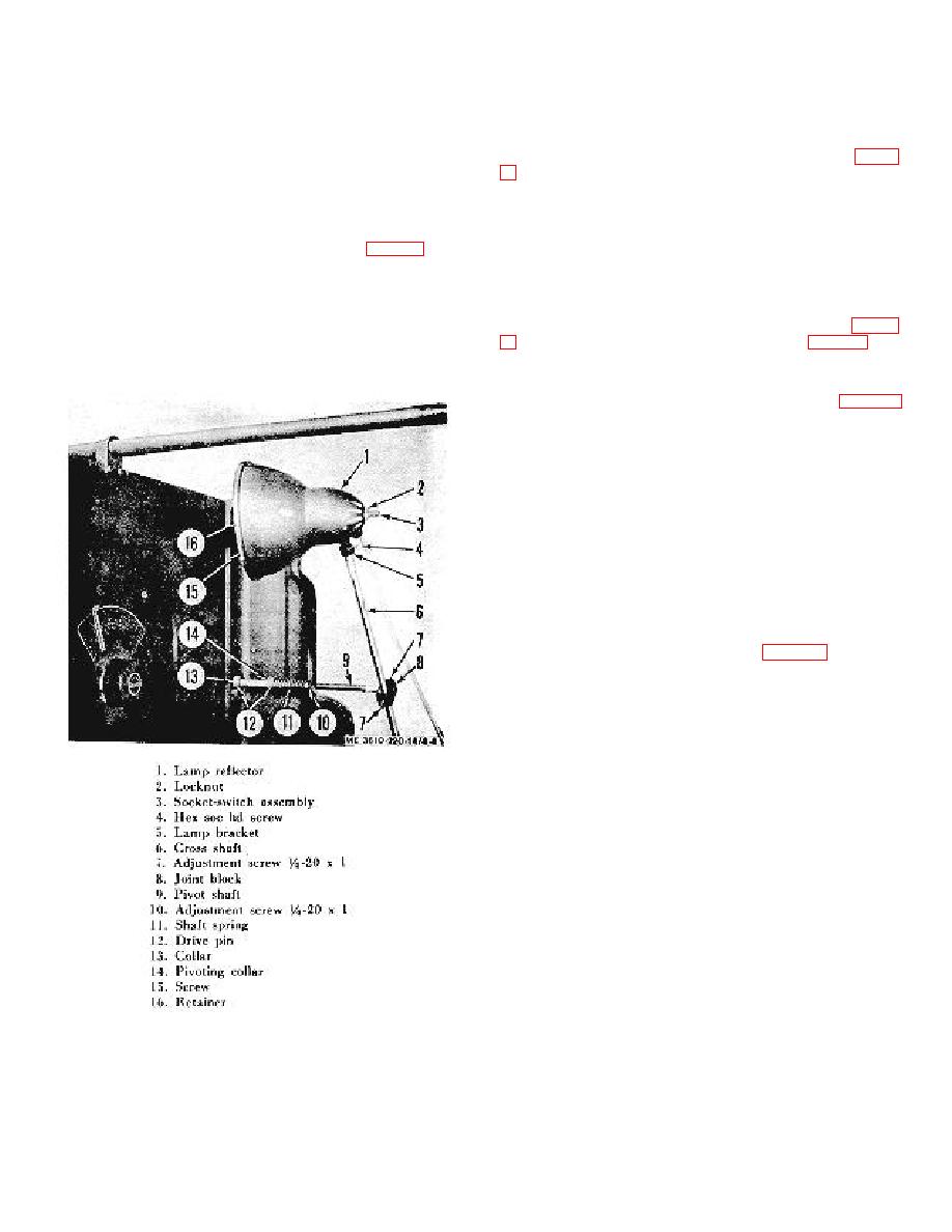
slide flash lamp assembly from pivot shaft (9). Remove
4-24. Copyboard Vacuum Control Switch and Vacuum
screw (4), on side of lamp bracket (5), to release the flash
Back Control Switch
lamp. Detach the socket-switch assembly (3) by removing
nut (2). Remove socket from the lamp reflector (1).
b. Installation. Mount the socket into lamp reflector (1)
with nut (2). Position the flash lamp assembly on the pivot
identical. Both switches are similarly installed, one for each
shaft (9), and tighten adjustment screw (7) to pivot shaft (9).
function.
from the copyboard vacuum control switch (1). Slide cover
plate (7}) from switch. Remove two screws on inside of
switch to release it from the copyboard frame (9). Disconnect
wire leads from switch. Loosen the locknut (5) to release the
vacuum control switch from nipple (6).
c. Installation. Attach the vacuum control switch (1)
with locknut (5). Mount the vacuum control switch to the
copyboard frame (9) with two screws. Connect loose leads to
switch terminals. Slide cover plate (7) over switch and retain
with screws (8).
4-25. Transparency Holder Light Switch
cover (3) from transparency holder light switch (2). Loosen
two screws holding switch to copyboard frame (9).
Disconnect wires from switch terminals. Loosen locknut (5) to
release the switch from the nipple (6). Disconnect wire leads
from switch.
b. Installation. Attach the switch to nipple (6) with
locknut (5). Connect loose wire leads to switch terminals.
Mount the switch to the copyboard frame (9) with two screws.
Attach cover (3) with screws (4).
Figure 4-4. Flash lamp assembly, installed.
4-8


