TM 11-7025-210-23
Table 4-1 . Fuse Locations and Circuits Protected
FUSE
LOCATION
CIRCUIT
4A MDA
XPS (F1) *
+157V
5A MDX
XPS (F2) *
10V
2A MDX
XPS (F3) *
+25V
2A MDX
XPS (F4) *
25V
7A MDX
XPS (F5) *
117V
1/8A PICO
LOG (F1) **
PHASE 1 CLOCK
1/8A PICO
LOG (F2) **
PHASE 2 CLOCK
*
See figure 2-14.
**
See figure 2-13.
4-11. STATUS INDICATORS AND TROUBLESHOOTING
The status indicators (fig. 4-2) are light emitting diodes (LED) on the outside edges of five printed wire boards. You can
see the indicators by removing the pedestal cover. An explanation of the condition that exists when each indicator is lit is
shown in figure 4-2. Troubleshooting with these indicators is defined in table 4-2.
Table 4-2 provides data for identifying a faulty PWB or other fault. This table lists various conditions in which the ALARM
indicator and the status indicators will be lit or blinking. For each condition of the indicators there is a list of probable
causes, corrective actions, and maintenance procedures. If the fault cannot be isolated and repaired with this information,
go to paragraph 4-12 and do further troubleshooting with the aid of table 4-3.
NOTE
cause. You will be able to find other faults by noting which
indicators are lit or not lit and analysing the situation they
represent.
CAUTION
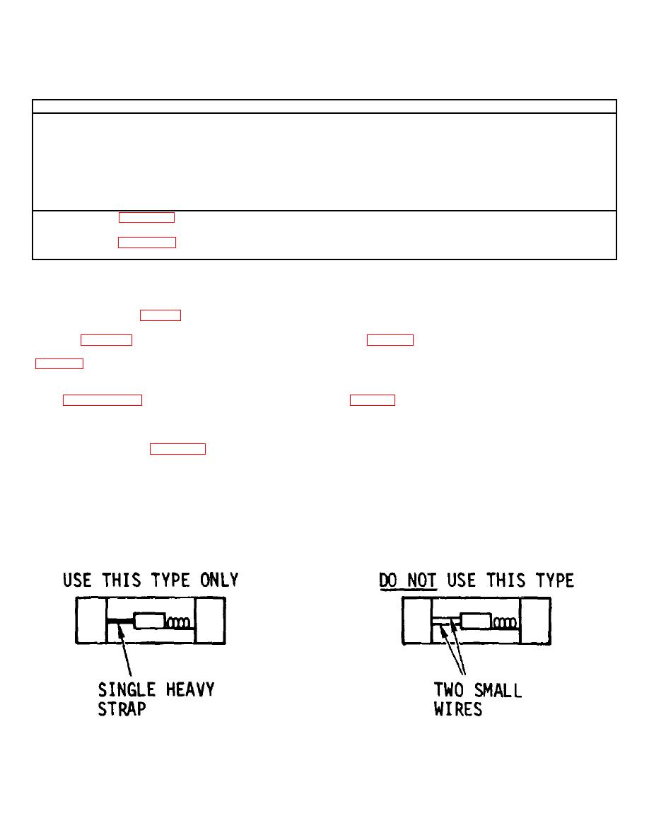
Replacement fuses must be the single strap type shown below.
4-6


