TM 11-7025-210-23
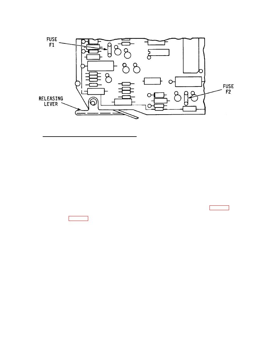
Figure 2-13. Pico Fuses F1/F2 on Logic Board
f.
Unbuffered Parallel Interface Board (CINT/2). The unbuffered parallel interface circuit board (CINT/2) is
installed in the bustle slot labeled INT where it engages the mother board. The CINT/2 board receives all data and
controls signals through a 25-pin connector. It contains logic to perform a parity check. The board also contains decode
circuitry to execute paper control commands, i.e., line feed, form feed, or slew. Finally, the CINT/2 board contains
interface logic for other control commands and status signals such as bell and low paper. The line printer receives one full
line of data at the maximum transfer rate of 60, 000 characters/second. After the full line of data has been received by the
logic board (LOG/8) from the interface board (CINT/2), the logic board will send a busy signal to the data source through
the interface board. During this "busy" time, the line printer will execute any paper feeding commands received, print the
line of data, and execute a line feed. While the line feed is being executed, another line of data may be entered from the
data source.
2-5. POWER SUPPLY
Power enters the line printer through the power cord and goes through the cover interlock switch and the power switch.
Both of these switches must be closed before power exists on the power control (XPS/3) board (fig. 2-14).
The power control board (fig. 2-15) receives power from the 117 V ac power source and, through the power transformer
located on the main frame, supplies low voltage unregulated power to the power supply regulator board (PSR/1). In
addition, the XPS board contains all power supply fuses, the ac line filter, motor circuit, and line feed solenoid driver.
The incoming ac power passes through the line filter inside the ac switch box. The line filter prevents line-generated RFI
from entering the power supplies and also prevents unit-generated RFI from conducting back into the ac line. The fuse F5
protects the 117 V ac primary circuit.
2-11


