
TM 11-7025-210-23
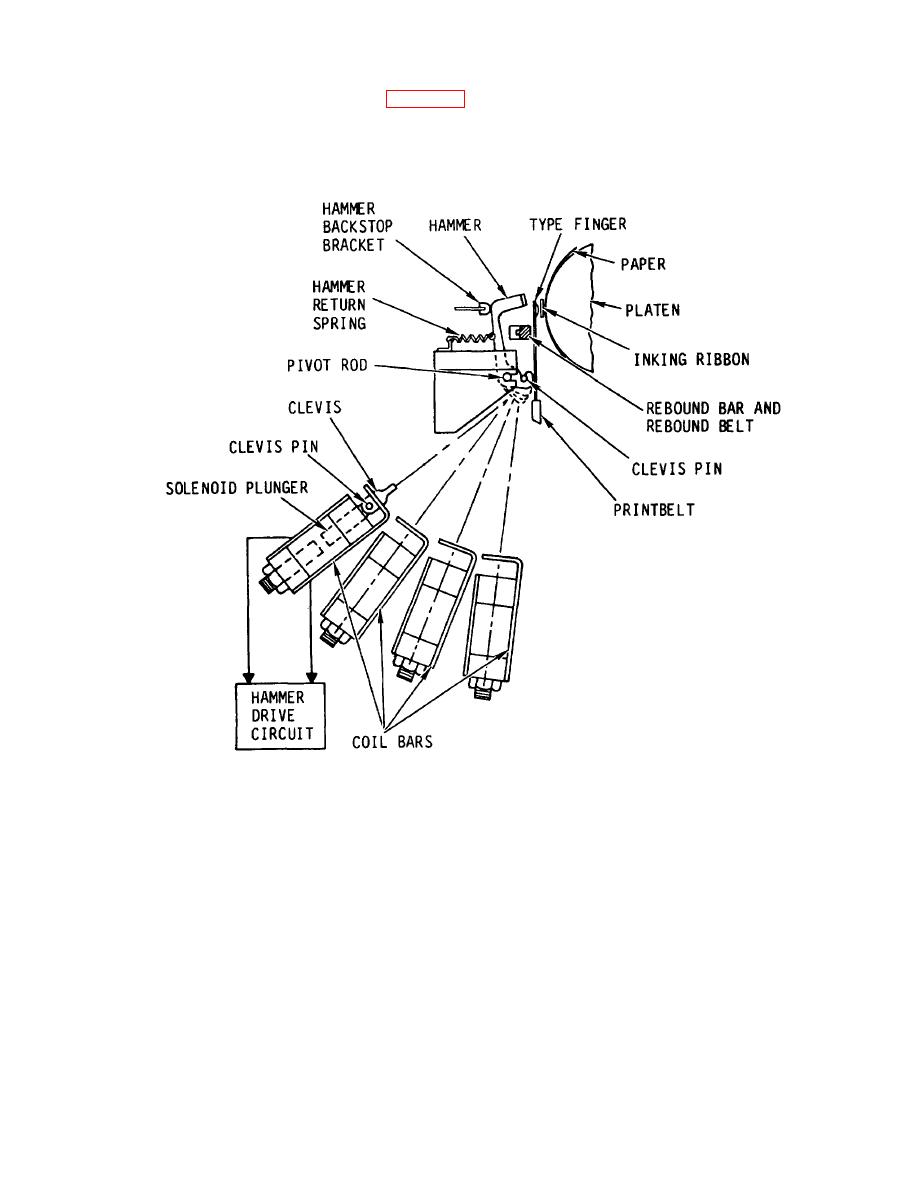
(2) All of the individual hammers (fig. 2-6) are mounted on a common pivot rod. Each hammer is
connected by its clevis to a solenoid plunger. The clevis engages a curved slot at the base of the hammer. The other end
of the clevis is linked to the solenoid plunger. When the solenoid coil is energized by the hammer drive circuit, the clevis is
pulled down by the plunger, causing the hammer to pivot forward about the pivot rod. The face of the hammer travels
forward approximately 0.077 inch (2.0 mm) while being pulled by the clevis.
Figure 2-6. Hammer Impact Process
(3) The swinging of a hammer against a type finger is electronically controlled by a timing process which
uses an electronic buffer storage and counting system. When a character printout is selected by input data, the line printer
buffers or stores the input data and permits multiple hammer firing when selected type fingers are in the correct position.
(4) The solenoids are mounted and spaced uniformly in banks on the coil bar assemblies. There are four
coil bar assemblies mounted parallel to each other with an angular displacement. The bars are supported at the ends of
the belt pulley castings.
2-5
