TM 10-3610-202-14
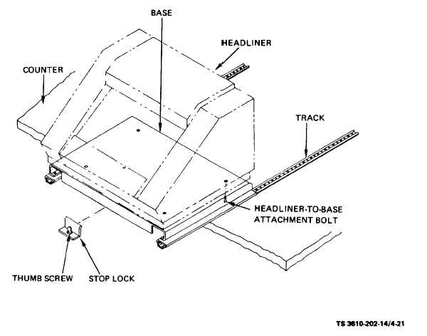
Figure 4-21. Headliner Composing Machine, Removal and Installation
(3)roll the headliner composing machine and attached
base toward the front of the headliner counter and
remove.
(4)
Remove the four mounting bolts attaching
the headliner composing machine to the base and
remove the composing machine.
b.
Installation . To install the headliner composing
machine proceed as follows:
(1)
Mount the headliner composing machine
on the base and secure with four mounting bolts.
(2)
Position
the
headliner
composing
machine and base on the tracks and push the entire
assembly toward shelter wall.
(3)
Install the stop lock on headliner counter
and secure with thumbscrew.
(4)
Plug the headliner composing machine
electrical connector into wall receptacle.
Section XV. MAINTENANCE OF PHOTOTRAY ASSEMBLY
4-34. General.
A three level phototray assembly (see fig. 4-22)
for use in photographic developing consisting of three
plastic trays and metal frame is located on the headliner
counter, between the utility sink and Varitype Headliner.
4-41