TM 5-3610-294-13&P
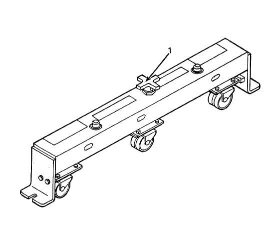
2-11. TRANSPORTER ASSEMBLY. Refer to figure 2-10 for location of controls and indicators.
a.
Hand Knob (1)-When turned clockwise, lowers wheels to allow movement of equipment assembly attached to
transporter assemblies. When turned counterclockwise, raises wheels to allow equipment assembly to set on
shelter floor.
Figure 2-10. Transporter Assembly
2-12