TM 5-3610-294-13&P
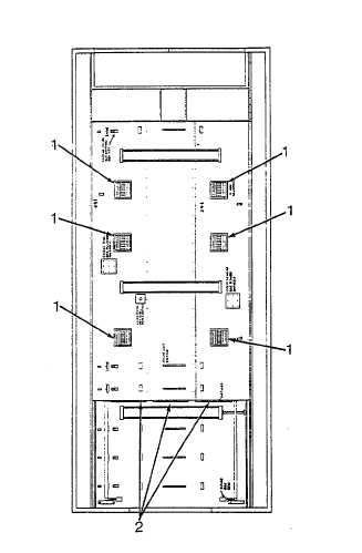
2-8. AIR CONDITIONER CEILING DUCT ASSEMBLY. Refer to Figure 2-7 for location of operator's controls and
indicators. The ducting and vent assemblies provide even distribution of conditioned air throughout the shelter.
a.
Ceiling Registers, Hand Operated (6 each) (1)-Allows the operator to control the flow of air to the interior of the
shelter.
b.
End Registers, (3 each) (2)-Provides flow of air to the front of the shelter.
Figure 2-7. Air Conditioner Ceiling Duct Assembly
(Looking at ceiling)
2-9

