TM 10-3610-202-14
(b) Remove the nuts and washers,
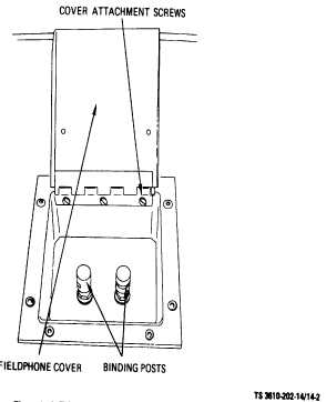
located
on the interior wall of the shelter, from the binding post.
(See fig. 14-2.)
Figure 14-2. Telephone Binding Post, Removal and Installation
(c) Remove the binding post by pulling
out from exterior end.
(2)
Repair. Repair of the telephone binding
posts consists of replacement.
(3)
Installation. Install new binding posts as
follows:
NOTE
Installation
procedure
are
identical for each binding post.
NOTE
Assure that binding post am
positioned
so
that
telephone
wires can be invited from the
underside of the post
(a) Insert two binding posts through
holes in assembly frame and shelter wall.
(b) Install washers and nuts on the
binding posts and tighten.
(c) Close hinged fieldphone connection
cover.
c.
Hinged Cover.
(1)
Removal. Remove the hinged fieldphone
connection cover as follows:
(a) Raise cover and remove the screws
attaching the cover hinge to the frame assembly. (See
fig. 19-2.)
(b) Remove hinged cover.
(c) Remove attaching screws from
nomenclature placard and remove placard. (See fig.
14-1.)
(2)
Repair. Repair of the fieldphone hinged
cover consists of replacement.
(3)
Installation. Install new hinged fieldphone
connection cover as follows:
(a) Position the nomenclature placard
on the replacement cover and match drill attaching
holes.
(b) Secure
placard
with
attaching
screws.
(c) Position removed cover hinge on
new hinge and match drill attaching holes.
(d) Weld new hinge to cover.
(e) Position hinged cover on assembly
frame and attach with screws.
(f) Close cover.
14-2