TM 10-3810-202-14
CHAPTER 16
REPAIR OF LEVEL INDICATOR ASSEMBLY
16-1. General.
Two recessed level gages are installed on the
shelter. One gage is installed on the outside wall of the
shelter to the left of the shelter door. The second
is installed at the same level on the outer roadside wall
of the shelter. The gages are used to level the shelter
during installation on uneven terrain. (See fig. 16-1.)
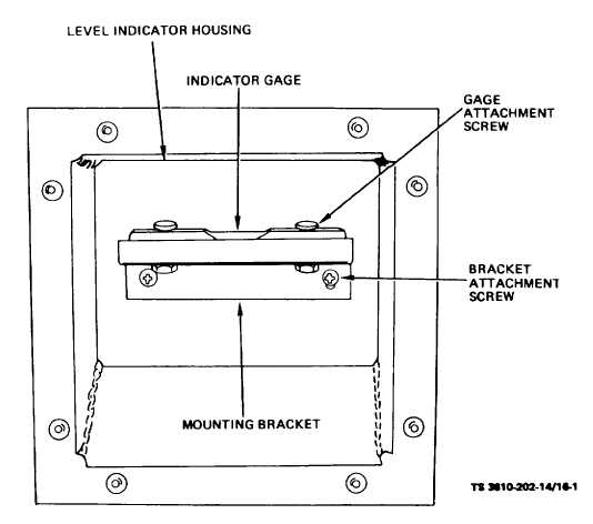
Figure 16-1. Level Indicator Gage and Housing, Removal and Installation
1
6-2. Level Indicator Assembly.
a. Removal.
Remove
the
level
indicator
assemblies as follows:
NOTE
Removal procedures are identical
for both assemblies.
(1)
Drill out the blind rivets securing the level
indicator assembly to the shelter wall and remove the
assembly. (See fig. 16-1.)
(2)
Remove sealant from shelter wall.
b.
Installation. Install the level indicators as
follows:
(1)
Using heavy paper, construct a mounting
hole location template by placing the paper on the
removed indicator assembly and mark mounting holes.
(2)
Using the template as a guide, drill
mounting holes in the replacement indicator assembly.
(3)
Apply sealant to back of assembly and
position in shelter wall.
(4)
Secure with blind rivets.
16-1/(16-2 blank)