
TM 11-7025-210-23
4-46. REMOVE/REPLACE HAMMERBANK ASSEMBLY (CONT)
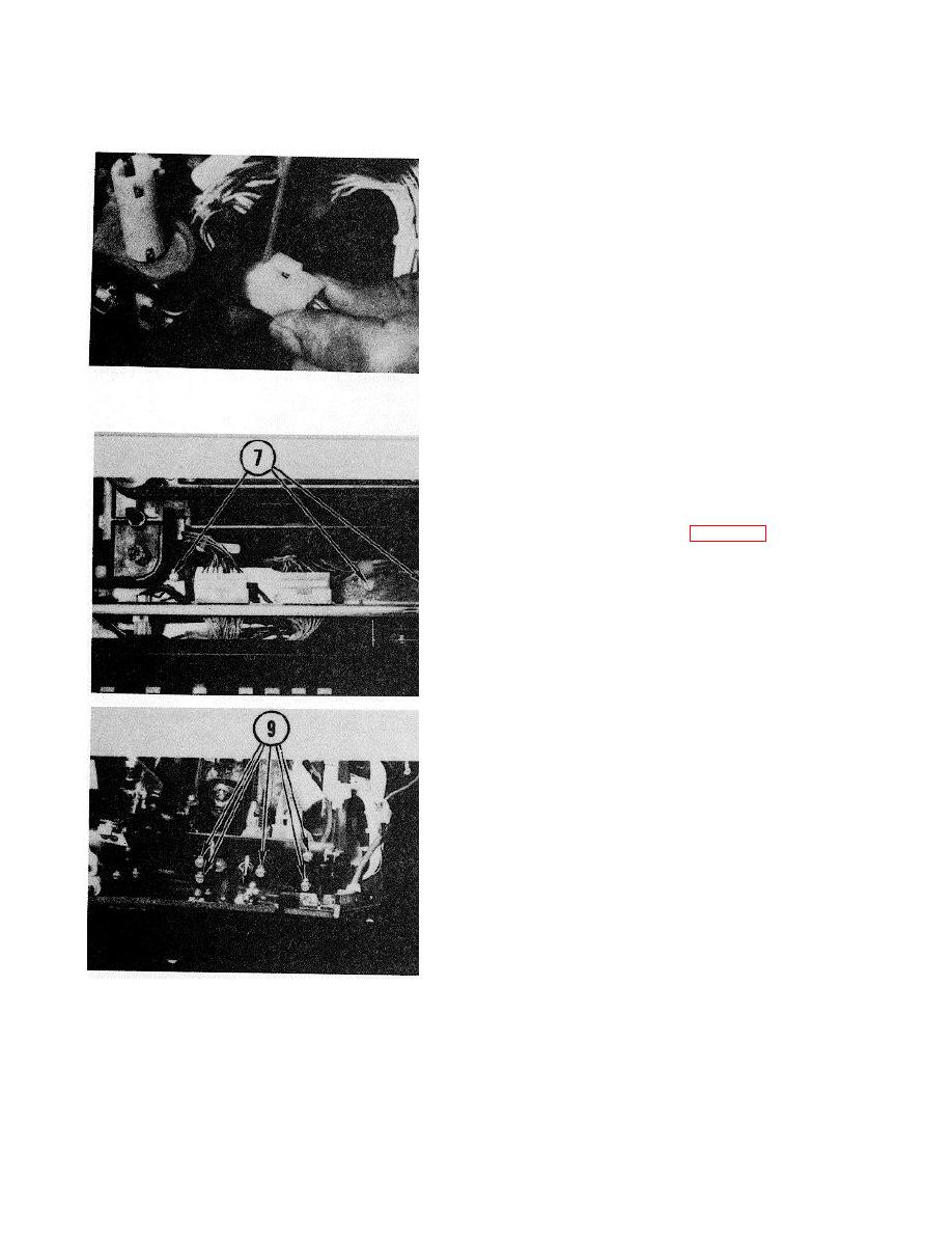
6. Pry out photocell connector.
7. Remove screws from cable clamps.
8. Remove left drive belt (para 4-33, steps 2-5).
CAUTION
Do not loosen the three smaller screws
securing alinement bars to side frame.
Adjustment of these bars is critical and can
only be done at the factory.
9. Remove five screws on both sides of printer.
Remove belt tension screw on right side of
assembly.
NOTE
It may be necessary to remove plastic shield
from each side plate of chassis so
hammerbank assembly will clear chassis.
Retain plastic shields.
4-108
