
TM 11-7025-210-23
4-42. ADJUST STROBE DETECTOR ASSEMBLY (CONT)
NOTE
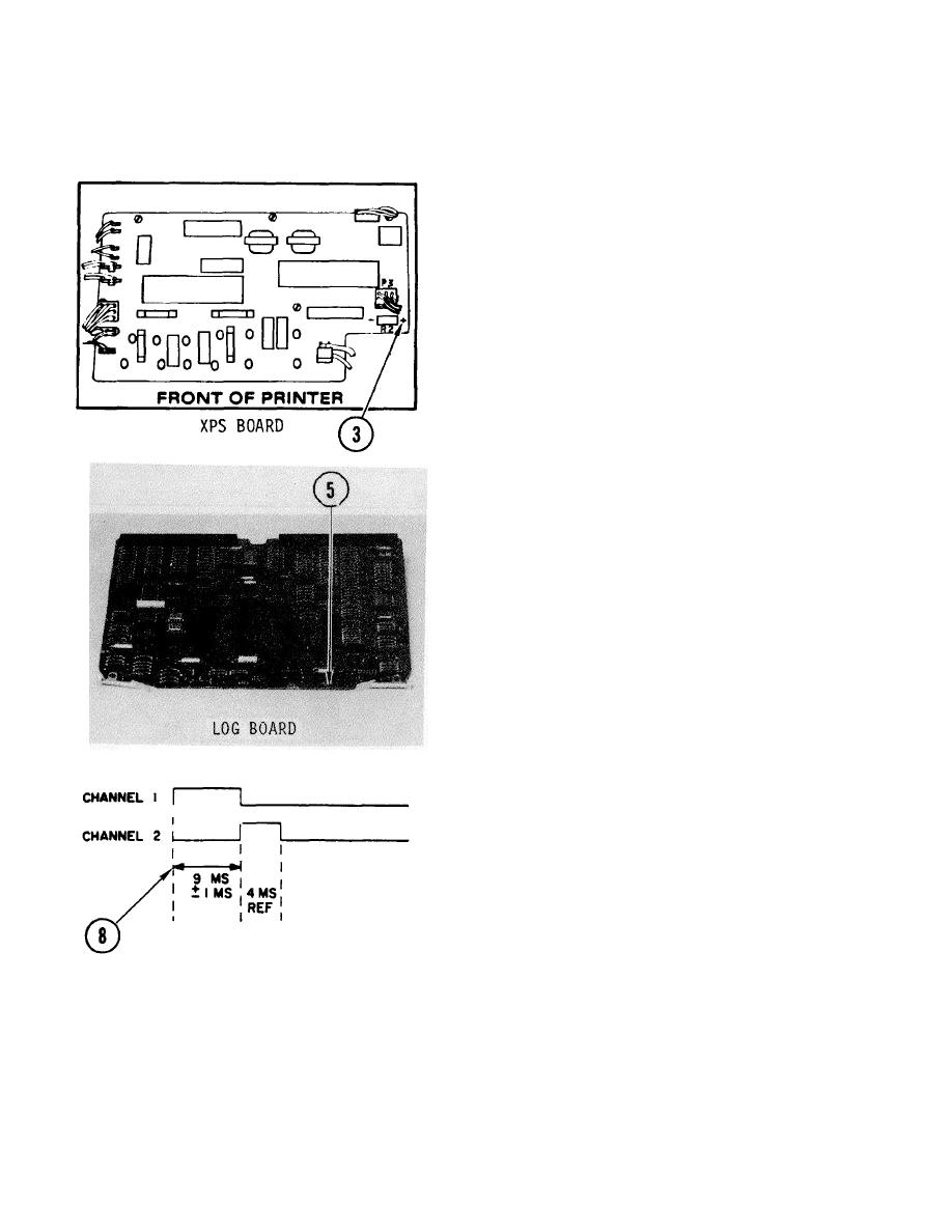
Make sure to connect channel 1 probe to R2
lead nearest right end of board.
3.
Connect channel 1 probe as shown, to resistor R2
located at right side of XPS board near P3.
4.
Remove front pedestal cover.
5.
Connect channel 2 to TP1 on LOG board.
6.
Pull up top cover interlock switch. Tape down paper out
switch.
7.
Power on. Start motor. Press LINEFEED button
repeatedly to get a pattern on the oscilloscope screen.
8.
Check if time to the leading edge of pulse in channel 2 is
9 ms + 1 ms.
4-97
