
TM 11-7025-210-10
2-9. OPERATION OF AUXILIARY EQUIPMENT
Auxiliary equipment consists of the VFU assembly, VFU punched tape, and the punch and splicer device.
a. VFU Assembly. The VFU assembly advances the paper and spaces the printing as desired. It consists of:
Sprocket Wheel. Holds and moves the VFU tape on traction pins
Detector Assembly. Reads the Form Feed (FF) and Vertical Tab (VT) code holes punched in the tape. It then
sends the information to the slew strobe assembly which moves and turns the VFU drive belt
Drive Belt. Moves the sprocket wheel
b. VFU Punched Tape. The VFU punched tape is opaque or mylar tape containing prepunched sprocket holes. FF and
VT code holes are punched in it with a punch and splicer device.
c. Punch and Splicer Device. This device is used to punch channel one (FF) code holes for Form Feed (FF) and channel
six (VT) code holes for Vertical Tab in the VFU tape.
A manual punch and splicer device is available as auxiliary equipment to prepare punched tape for use in the vertical
format unit (VFU).
2-10. USE OF VFU PUNCHED TAPE
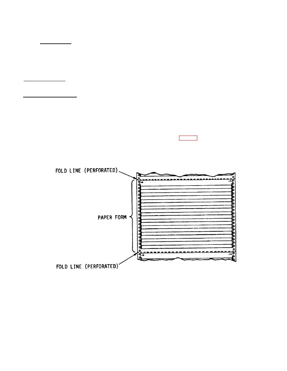
The VFU uses punched tape to advance continuous pin-feed (fan-fold) paper (fig. 2-2) through the printer. This type of
paper is divided by perforated fold lines into sections known as forms. Normally, print should appear on the form and not
on the fold-lines. The VFU punched tape is used to advance the paper and space the printing properly (as desired) within
the form.
Figure 2-2. Continuous Pin-Feed (Fan-Fold) Paper
2-18
