TM 11-6780-225-12
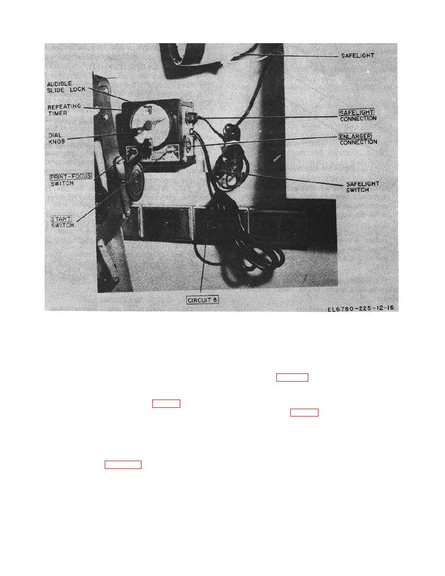
Figure 2-5. Repeating timer interconnection diagram.
i. Heating and Air-Conditioning System.
Set
WARNING
registers of the louvres in the open or closed position
Do not operate the space heater unless the
according to weather conditions.
exhaust pipe is installed in a vertical
position with the opening at the top.
thermostats (fig. 1-18) to desired temperature according
to weather conditions.
g. Space Heater Exhaust Pipe and Condensate
Drain.
k. Door Safety Lock Releases. With the entrance
Remove the space heater exhaust cap (fig. 5-1) and the
door and escape door locked from the outside, remove
condensate drain cap and install the exhaust pipe.
the thumbscrew (fig. 2-6) on the inside of each door to
NOTE
determine that the door safety lock releases are
operative.
Check to see that the refrigerator line
plug is connected to circuit 4 (fig. 1-
l. Equipment Covered by Manuals Stored in
18).
Darkroom File Cabinet.
Refer to the equipment
h. Refrigerator.
With a screwdriver, set the
manuals stored in the darkroom file cabinet for
temperature control (fig.
2-10) to 40 (4.5 ),
F
C
instructions for the refrigerator, dehumidifier and other
components of the darkroom not covered by technical
checking the temperature against a thermometer (fig. 1-
3).
manuals.
Change
2-6


