TM 11-6730-235-35
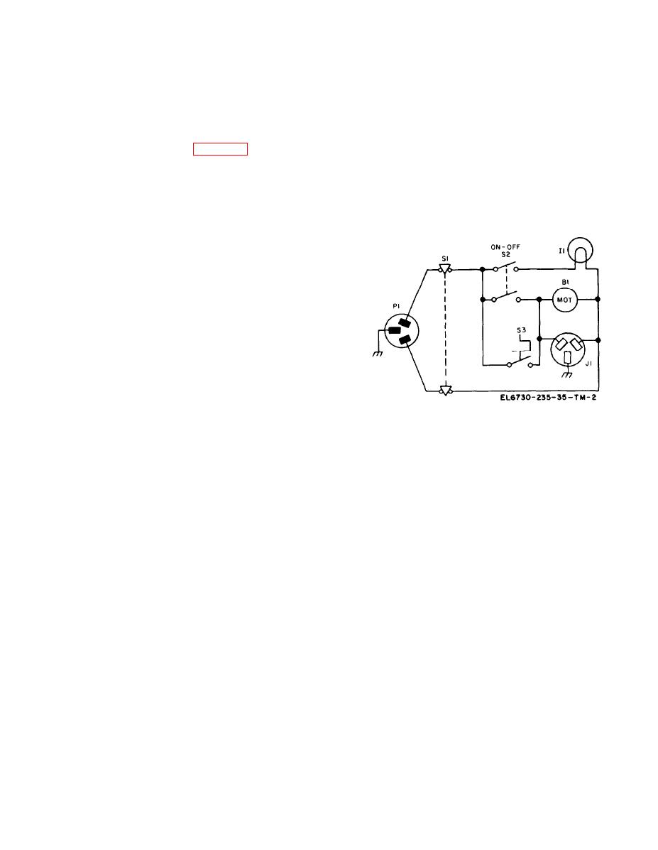
contacts removes power from the blower motor,
2-3. Electrical Operation
which had been operating even though power had
The electrical operation of the projector involves
been turned off.
the application of power to the convenience outlet
on the projector, the application of power to the
d. If the top plate assembly of the projector is
projection lamp, and the control of the power
opened for maintenance of items in the case
applied to the blower motor in the projector. The
assembly or on the top plate assembly, the
electrical elements involved in these operations are
interlock arm of the case assembly is actuated.
shown schematically in figure 2-2.
When this arm is actuated, the contacts of inter-
lock switch S1 open. Opening these contacts
a. Power is connected to the projector by line
removes power from convenience outlet J1, lamp
plug P1. Whenever the top plate assembly of the
I1, and blower motor B1, regardless of the states of
projector is in the closed position, the contacts of
ON-OFF switch S2 and thermal switch S3.
interlock switch S1 are closed. With interlock
switch S1 contacts closed, power is routed to
convenience outlet J1.
b. When ON-OFF switch S2 is placed in the on
position, power is also applied to projection lamp
I1 and to blower motor B1. As a result, projection
lamp I1 lights and blower motor B1 drives a
cooling fan for the lamp.
c. When the heat produced by the light
radiation from lamp I1 reaches 135F (57C), the
contacts of thermal switch S3 close and parallel the
closed contacts of ON-OFF switch S2. When
ON-OFF switch S2 is placed in the off position,
S2 contacts open. The parallel connection provided
by thermal switch S3 contacts remain, however,
until the temperature drops to 131F (54C). At
Figure 2-2. Projector, electrical schematic diagram.
that time, the opening of the thermal switch S3
2-3


