
TM 11-6720-242-35
40
Screw (H548)
24
AEC Assembly (IA1A1)
41
Washer (H549)
25
Screw (H2-H7)
42
Clamp (MP816)
26
Assembly, motor, gears, and tachometer-
43
Puck switch (S1)
generator (lA1A3)
44
Screw (H214)
27
Screw (H150)
45
Actuator (MP1)
28
Screw (M144-145)
46
Screw (H1)
29
Pin (MP814-815)
47
Pin (MP264)
30
Motor support (MP404)
48
Terminal (E3-E4)
31
Screw (H87-H89)
49
Identification plabe (MP266)
32
Shield (MP362)
50
Screw (H176185)
33
Screw (H208-209)
51
Pin (MP263)
34
Block (MP126)
52
Clamp (MP173-175)
35
Screw (H550-551)
53
Washer (H80-82)
36
Photo cell assembly (1A1A2)
54
Screw (MPH77)
37
Screw (H131-132)
55
Nut (H75-76)
38
Window (MP410)
198
Housing (MP204)
39
Bracket (MP128)
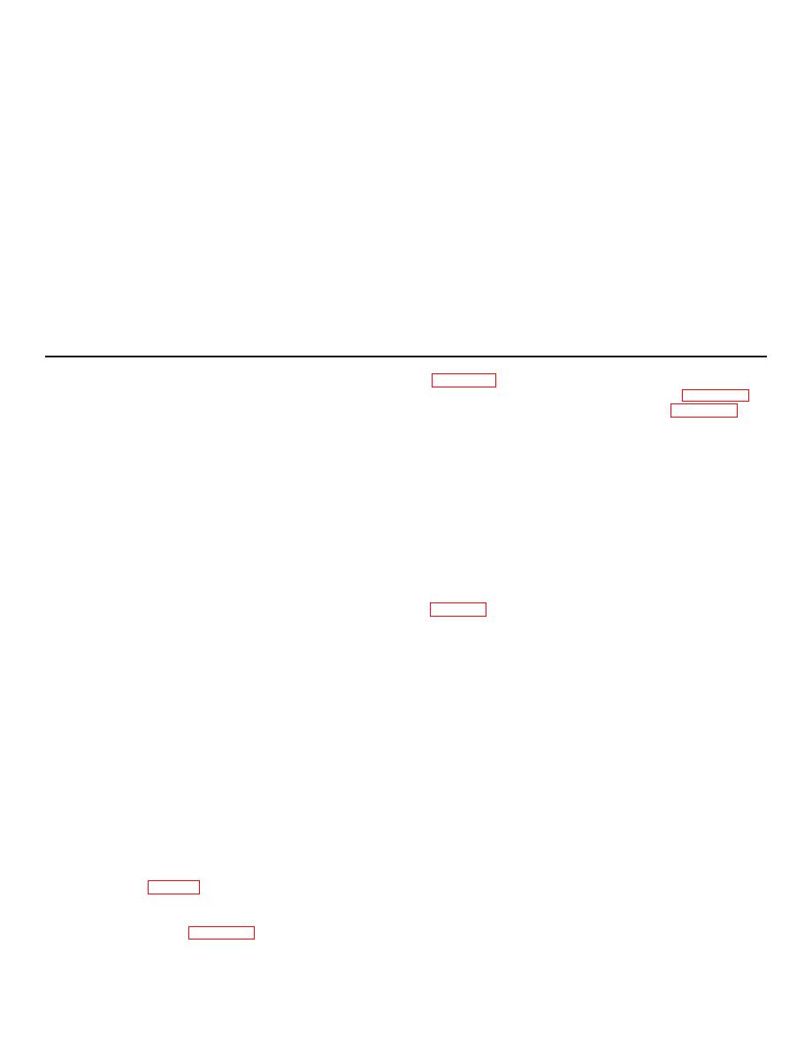
Figure 3-4(2)-Continued
a. Removal.
(2) Remove heat sink electrical connector
(1) Loosen the captive screw (2), washer (3),
(3) Remove heat sink assembly (para 3-22).
and dzus fastener securing the cover assembly (1) to
(4) Remove connector covers (para 3-17).
the chassis assembly (36).
(5) Remove the three remaining screws (25)
(2) Pull out the aec board assembly (4),
securing each electrical connector to the front panel
control board assembly (5) and scan board assembly (6)
(28).
from chassis assembly (36) to prevent damage.
(6) Remove interconnecting board assembly
(3) Remove the two screws (10) and washers
(35) from the three posts which attach it to panel (28) by
(11) securing the electrical connector (9).
removing three screws (26). Two of the attaching screws
Remove nut (12)
saddle washer (13), screw (14)
are located below electrical connector J7 at the outer
and clamp (15) securing the harness to the front panel.
edges of the board. The third screw is located in the
(4) Remove the four screws (17) securing the
lower center of the board. Remove the board. The three
heat sink assembly (16) to the chassis assembly (36).
post remain attached to interconnecting board assembly
Support the heat sink assembly after its removal to
(35).
prevent excessive strain on the wire connections.
b. Disassembly of Interconnecting Board Assembly
(5) Disconnect the wire leads from the circuit
breaker terminals.
(1) Remove two posts (1) by removing
(6) Remove nut (20) and washer (21)
screws (2) and washers (3).
securing the circuit breaker (18 or 10) to the front panel.
(2) Remove post (4) by removing screw (5)
(7) Withdraw the circuit breaker from the
and washer (6).
front panel.
b. Replacement.
NOTE
(1) Attach a new circuit breaker to the front
Although connectors 2J1(7), 2J2(11),
panel of the camera control in the reverse sequence the
and 2J3(9) are dissimilar, the
parts were removed. Apply glyptal to the threads of the
procedure for the removal of
attaching screws.
contacts from all three are basically
(2) Reinstall the heat sink assembly (16), the
plug-in scan board assembly (6), control board assembly
the same.
(5), and aec board assembly (4), and attach electrical
(3) Unsolder the wires from interconnecting
connector (9) and clamp (15).
board assembly (13).
(3) Attach the camera control cover (1) and
(4) Using extracting tool MS24256-R20, push
secure with captive screw and dzus fastener.
the contacts out of the connector, from the front.
3-28. Removal and Disassembly of Interconnecting
Board Assembly
(1) Remove the aec (4), control (5), and scan
board (6) assemblies from sub-classes (36). Remove
power supply assembly (para 3-25).
3-19
