
TM 11-6720-242-35
3-4. Localizing Troubles
bly to be plugged into a connector that is wired to the
a. General. If,. trouble was not localized at the
circuits shown.
organizational level by checks performed with Test Set,
f. Fabricating Scan Heat Sink Assembly Test
Camera LS-86A or by other means, refer to the
Fixture.
troubleshooting charts.
b. Troubleshooting Charts. The troubleshooting
(1) The heat sink assembly test fixture is not
supplied as a camera component. It must be made.
charts below provide continuity of analysis from
symptom, to probable trouble, to correction. The charts
(2) See figure 3-2 and construct a test fixture
will aid in tracing a malfunction. The detailed test
that permits connecting the heat sink to a connector that
procedures of paragraph 3-5 should then isolate the
is
wired
to
the
circuits
shown.
trouble to an assembly or part.
(1) Troubleshooting camera body.
Probable Cause
Corrective Action
Malfunction
Item
1
AEC malfunctioning .................. a.
Photocell assembly ............................ a.
Replace photocell assembly
b.
Defective servo motor, feedback
b.
Send AEC assembly to higher
resistor, or mechanism
category of maintenance.
2
Servo motor friction clutch
Worn or damaged parts ............................... Replace friction clutch (para 3-12).
defective.
3
ADAS not recording
a.
Defective RHA assembly.................... a.
Replace RHA assembly
photographically
b.
Damage to lens and mirror
b.
Send AEC assembly to higher
assembly
category of maintenance.
4
Sensitive (puck) switch
a.
Mounting alinement ............................ a.
Realign (para 3-1).
b.
Loose electrical connection ................ b.
Examine connections; secure
where necessary.
c.
Switch actuator adapter
c.
Send to higher category of
maintenance for
replacement.
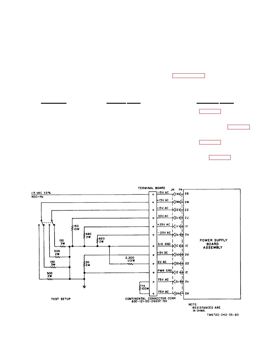
Figure 3-1. Power supply board assembly, test setup.
Change 1 3-3
