TM 11-6720-239-35
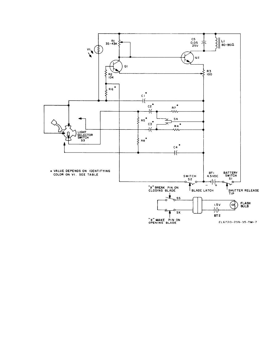
Shutter assembly, schematic diagram.
the center terminal of the flashbulb socket. Cur-
compensation switch S6 is forced open, placing
rent flows from the flashbulb socket side terminal,
resistors R4 and R7 into the timing circuit. These
through the shutter connecting cable to the sync
two resistors increase the charging time of capac-
connector plug. When the flashgun is being used,
itors C3 and C2. Without resistors R4 and R7 in
the sync connector is plugged into the camera's
the circuit, the intense light from the flashgun
shutter sync outlet, which is connected to the
would cause photocell VI to pass too much current
shutter flash circuit ( b above). From the flash
to the capacitors, causing them to charge too soon,
circuit, current flows through the shutter sync
and, in turn, close the shutter too soon.
outlet, the sync connector plug and the shutter
c. Flashgun. The flashgun receives power from
connecting cable to the negative (-) side of the
the self.-contained 1.5 volt battery B2. Current
flashgun battery B2.
flows from the positive (+) side of battery B2 to
1-7


