
TM 11-6720-239-35
moved toward the cocked position, flash switch S4
place. The focusing operation is accomplished as
opens.
follows:
(3) As the two blades reach the cocked posi-
(1) When focus button 1 (right) is pushed,
tion, the break pin on the closing blade causes
the focus bar assembly slides to the left, and Pulls
flash switch S3 to close and thus the closing blade
the attached end of the inner frame (top) with it.
is held by the electromagnet.
The shutter assembly is drawn toward the camera
body and the focal distance is reduced.
(4) When the shutter is tripped, the opening
blade snaps forward and the make pin closes flash
(2) When focus button 1 (left) is pushed, the
focus bar assembly slides to the right, and pulls
switch S4.
the attached end of the inner frame (top) with it.
(5) Both switches are now closed. If a flash-
The assembly is pushed away from the camera
gun is plugged into the shutter sync outlet, the
body, and the focal distance is increased.
flash circuit is completed and the flashbulb fires,
(6) When the exposure is completed, the clos-
b. Focusing Mechanism. The focusing mecha-
ing blade is released by the electromagnet thus
nism is mechanically coupled to the finder assem-
allowing flash switch S3 to return to its normally
bly by a focusing cam lever. As the focus bar
open position. The flash circuit is now open, and
assembly slides to the right, the focus bar bracket
the mechanical operating cycle is completed.
moves the focusing cam lever to the right, causing
the lever to exert a strain on the cam spring. As
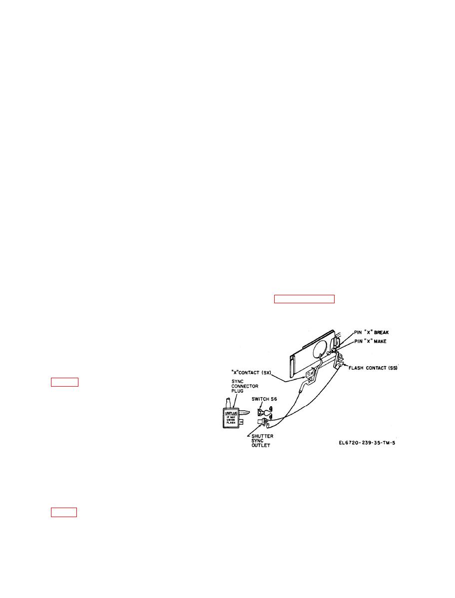
b. Flash Compensation. Flash compensation
the focus bar assembly slides to the right, the cam
switch S6 is used to set the timing circuit for
spring forces the focusing cam lever to the right,
flash operation. Flash compensation switch S6 is
so that the lever is in constant contact with the
normally closed, and acts as a bypass switch for
focus bar bracket. The focusing cam lever is con-
two resistors in the timing circuit. When the sync
nected to the rangefinder mechanisms in the
connector plug of the flashgun is plugged into the
finder assembly. Refer to section III of this chap-
shutter sync outlet, a plastic pin on the sync
ter for detailed functioning of the finder assem-
connector plug forces flash compensation switch
bly.
S6 to open, placing the two resistors into the tim-
ing circuit. The resistors increase exposure time
c. Fast Focus Mechanism. The fast focus mech-
to compensate for the intense light from the flash-
anism is used under certain conditions for fast
bulb. Refer to paragraph 110 for functioning of
(coarse) focusing. The fast focus scale is mounted
the timing circuit.
on the focus bar bracket above focusing button 1
(right). When the focus bar bracket moves, it
slides the fast focus scale past the fast focus indi-
cator. Fiducial marks on the fast focus scale indi-
cate approximate distance from camera to sub-
ject.
1-8. Flash Operation
a. Flash Circuit. The mechanical components of
the flash circuit are the flash switches S3, S4, S9,
and S10 and the shutter sync outlet. The mechani-
cal components operate as follows:
(1) Before the shutter is cocked, the flash
switch S3 is open and the make pin on the open-
ing blade is holding flash switch S4 closed.
(2) As the opening and the closing blades are
FUNCTIONING OF FINDER ASSEMBLY AND ELECTRICAL CIRCUITS
Section Ill.
subject strikes the objective lens and rangefinder
lens simultaneously. The image projected through
the objective lens and beam splitter to the eye lens
a. Rangefinder. The light reflected from the
