TM 10-3610-202-14
(2)Remove the composing machine.
b.
Installation . To install the composing machine
proceed as follows:
(1)
Position the composing machine over the
four mounting holes in the stand assembly top.
(2)
Insert and finger tighten the four attach
bolts from the underside of the stand assembly top.
(3)
Tighten the four attach bolts with a socket
wrench.
4-23. Composing Machine Stand.
The composing machine stand which is of steel
construction is mounted on the front shelter wall to the
left of and below the air conditioner unit.
a.
Inspection Inspect the composing machine
stand assembly for security of mounting, general
condition of the stand and condition and security of the
shock mounts. Replace as required.
b.
Removal To remove the composing machine
stand assembly proceed as follows:
(1)
Using a socket wrench remove the four
recessed attaching bolts securing the composing
machine to the stand assembly.
(2)
Remove the composing machine.
(3)
Remove the two attaching bolts from the
body of the stand assembly at the point where it is
secured to the forward shelter wall. (See fig. 4-14.)
(4)
Remove the composing machine stand
assembly.
c.
Installation To install a new composing
machine stand assembly proceed as follows:
(1)
Using heavy paper, construct a mounting
hole location template by placing the paper on the
removed stand assembly and marking mounting holes.
(2)
Using the template as a guide, drill
mounting holes in the replacement stand assembly.
(3)
Position replacement stand assembly
against shelter wall and align mounting holes with wall
receptacle.
(4)
Insert mounting bolts and tighten.
(5)
Position the composing machine over the
four mounting holes in the stand assembly top.
(6)
Insert and finger tighten the four attach
bolts from the underside of the stand assembly top.
(7)
Tighten the four attach bolts with a socket
wrench.
Section X. MAINTENANCE OF CAMERA MODIFICATION
4-24. General.
The vertical process camera is modified for use in
the editorial and photomechanical shelter system by
means of a clamp-type latching clip installed to retain
the film case cover in the closed position during use and
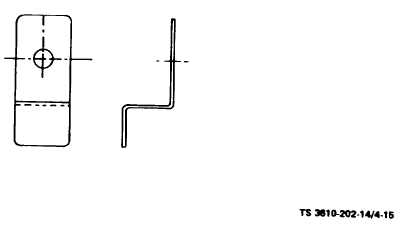
shipment or storage. (See fig. 4-15.)
Figure 4-15. Camera Modification Clamp
4-25. Camera Modification.
a.
Removal. Remove the camera film case cover
latching clamps as follows:
(1)
Remove the capscrew which attaches the
clamp at the right rear corner of the film case. (See fig.
4-16.)
4-34