TM 5-3610-295-13&P-1
4-39. LEVEL INDICATOR ASSEMBLY. - Continued
b. Replace. - Continued. (See Figure 4-50.)
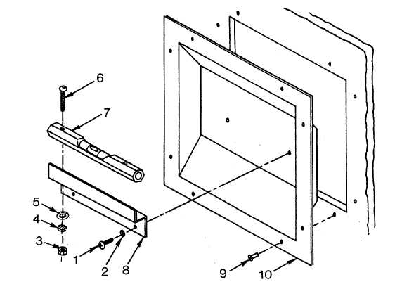
Figure 4-50. Level Indicator Assembly
(5)
Install receptacle frame (10) to shelter wall and secure with rivets (9). Installation procedures are
identical for both assemblies. Seal between receptacle frame and shelter wall with RTV (3, Appendix E).
(6)
Install level (7), screws (6), flat washers (5), lockwashers (4), and nuts (3) to bracket (8).
(7)
Install level bracket (8), screws (1), and lockwashers (2) to receptacle frame (10).
c. Repair. (See Figure 4-50.)
Repair of level indicator assembly is limited to replacement of the gage. Refer to paragraph b. above.
4-117